5
• The expansion valve is an electronic type, it is controlled by
the thermistors that are added in the circuit. Each expansion
valve can control a range of air handler units’ sizes.
• The selected air handler unit must be designed for R410A.
• Extraneous substances (including mineral oils or moisture)
must be prevented from getting mixed into the system.
• SST: saturated suction temperature at exit of air handler
unit.
3. Selecting the capacity setting adaptor (see accessories)
• The corresponding capacity setting adaptor needs to be
selected depending on the expansion valve (See Table 3).
• Connect the correct selected capacity setting adaptor to
X24A (A1P). (See Figure 9.)
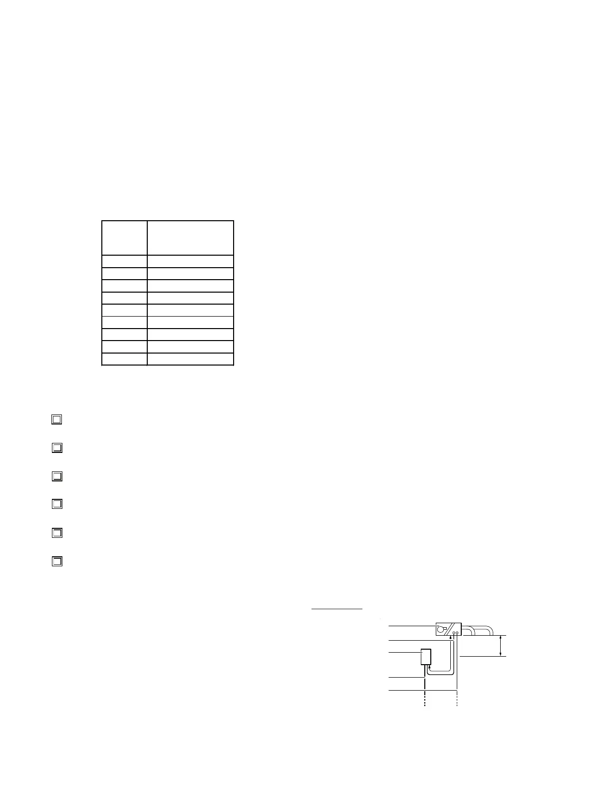
Capacity setting
adaptor label
(indication)
63 J71
80 J90
100 J112
125 J140
140 J160
200 J224
250 J280
400 J22
500 J28
Table 3
Use care during construction and check the following items after
installation is nished.
Are thermi s tors fi xed fi rml y?
Thermistors may come loose.
Is the freeze-up setting done correctly?
The air handler may freeze up.
Is the control box fixed firmly?
The unit may drop, vibrate or make noise.
Do electrical connection comply with specifications?
The unit may malfunction or components may burn out.
Are wiring and piping correct?
The unit may malfuncton or components may burn out.
Is the unit safely grounded?
Dangerous or electrical leakage.
This is a class A product. In a domestic environment, this product
may cause radio interference, in which case the user may be
required to take adequate measures.
Select an installation site where the following conditions are met
and that meets your customer’s approval.
• The kits (expansion valve and control box) are designed for
both indoor and outdoor installation.
• Do not install the option boxes in or on the outdoor unit.
• Do not put the option boxes in direct sunlight. Direct sunlight
will increase the temperature inside the option boxes and
may reduce its lifetime and inuence its operation.
• Choose a at and strong mounting surface.
• Ambient temperature of the control box is between 14°F
(-10°C) and 104°F (40°C).
• Keep the space in front of the boxes free for future mainte-
nance.
• Keep air handler unit, power supply wiring and transmission
wiring at least 3-1/4 ft. (1 m) away from televisions and radi-
os. This is to prevent image interference and noise in those
electrical appliances. (Noise may be generated depending
on the conditions under which the electric wave is generated,
even if 3-1/4 ft. (1 m) is kept.)
• Make sure the control box is installed horizontally. Screw nuts
position must be downwards.
Do not install or operate the unit in rooms mentioned below.
- Where mineral oil, like cutting oil is present.
- Where the air contains high levels of salt such as air near
the ocean.
- Where sulfurous gas is present such as that in areas of hot
spring.
- In vehicles or vessels.
- Where voltage uctuates frequently such as in factory sites.
- Where high concentration of vapor or spray are present.
- Where machines generating electromagnetic waves are
present.
- Where acidic or alkaline vapor is present.
- The option boxes must be installed with entrances
downward.
NOTE: The use of a heat shield is strongly recommended when
brazing to avoid burning the serial plate or the nish of the unit.
Heat trap or wet rags must be used to protect heat sensitive
components such as service valves EEV, thermistor and pressure
sensor.
• For refrigerant piping of outdoor unit, refer to the installation
manual supplied with the outdoor unit.
• Follow the outdoor unit specications for additional charging,
piping diameter and installation.
• The maximum allowed piping length depends on the con-
nected outdoor model.
Piping Limits
L
A
3
2
5
4
Figure 2




 To Next Page