3
Refer to this manual in combination with the instructions provided
with the air handler for the correct installation procedure.
The electrical characteristics of the air handler, the EEV kit and
the building power supply must agree.
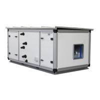
• For installation of the air handler unit, refer to the air handler
unit’s installation manual.
• Never operate the air conditioner with the discharge pipe
thermistor (R3T), suction pipe thermistor (R2T) and pressure
sensors (S1NPH, S1NPL) removed. Such operation may
burn out the compressor.
• The equipment is not intended for use in a potentially
explosive atmosphere.
The following table lists the accessories that are compatible with
this kit:
Description Pa rt QTY.
The rmi s tor (R1T) 1
Thermistor (R3T/R2T)
8-1/4 ft. (2.5m) cabl e
2
Insulation sheet 2
Rubber sheet 2
Wire to wire splice 6
Installation
& operation manual
1
Tie wrap 6
Capacity setting adaptor 10
Stopper (closing cup) 1
Conduit mounting plate
(wi th s eal i ng ga s ke t) P/N: 0121V00023
PT Screw (K50x10mm)
P/N: 0163M00318
2
Insulation tube
P/N: 0161V00001
1
Obligatory Accessory
Description Pa rt
Expansion valve kit EKEXV
Refer to the Valve Kit Installation section for instructions on how to
install the Expansion valve kit.
Optional Accessory
Description Pa rt Qty.
Remote control
BRC1E73, BRC2A71, BRC1E72
6 710
3
2 11
5 14
9 8
1
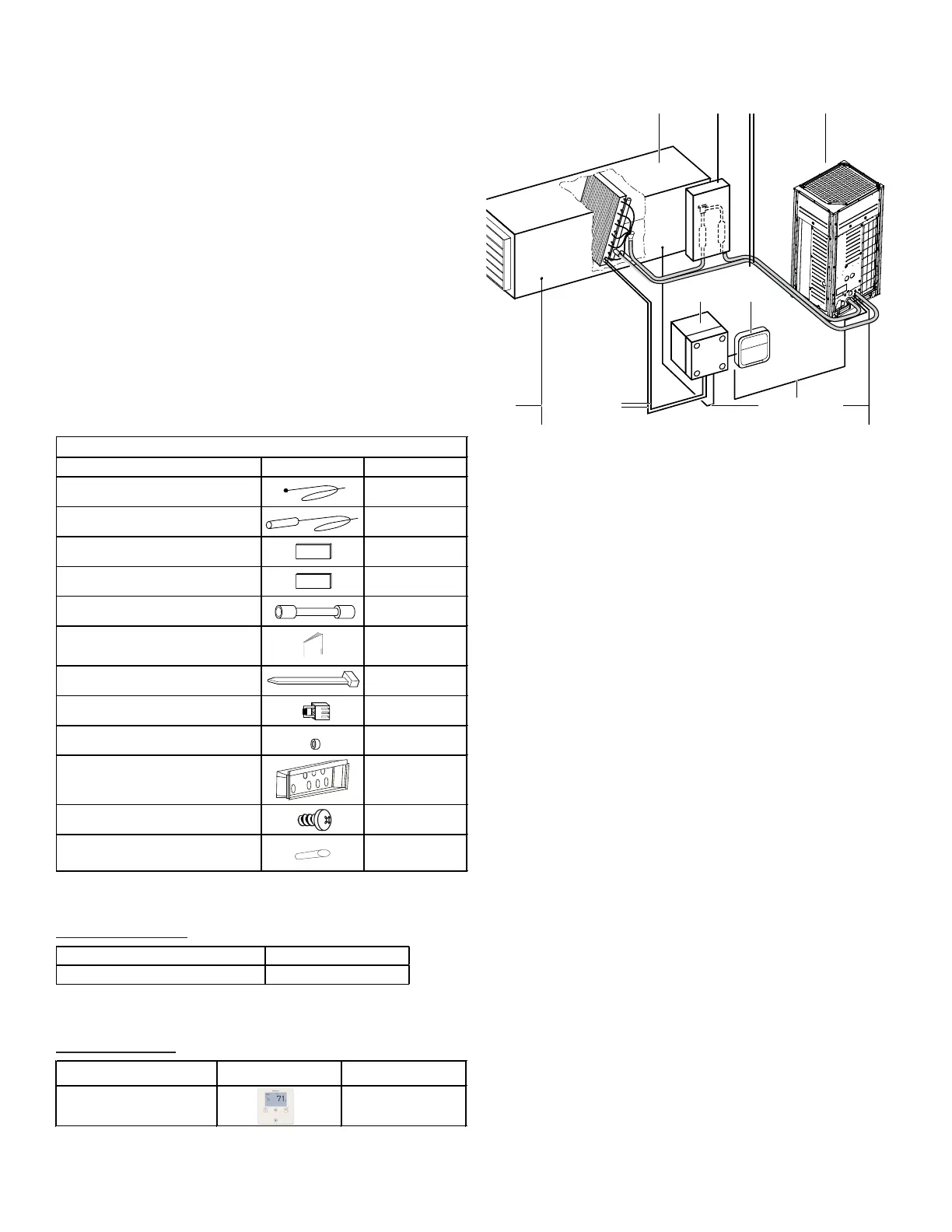
Figure 1
Parts and components
1. Outdoor Unit
2. Control Box
3. Air Handler Unit (Field supplied)
4. Field Piping (Field supplied)
5. Expansion Valve Kit
6. Wiring connections
7. Outdoor Unit Power Supply
8. Control Box Wiring
(Power supply & communication between control box and out
door unit)
9. Air Handler unit thermistors
10. Power supply and control wiring for air handler unit and con-
trol. (Power supply is separate from the outdoor unit.)
11. Air thermistor control for air handler unit
12. Remote control
 Loading...