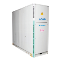
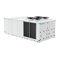
23
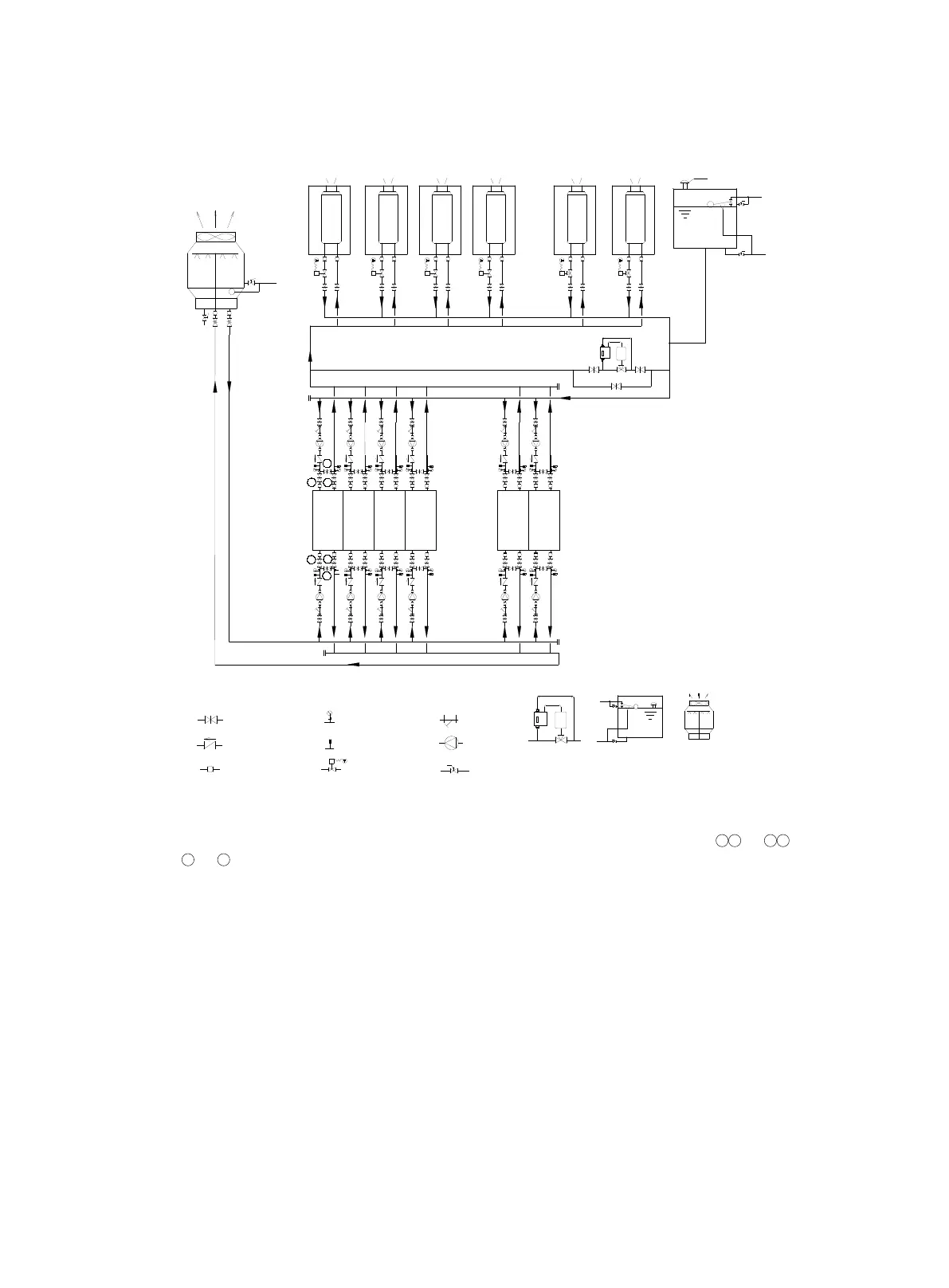
Installation illustration for water system of multi-unit combination (separate pumps
for each unit):
ELECTRIC 2-WAY VALVE
THERMOMETER
PRESSURE GAUGE
GATE VALVE
FLEXIBLE CONNECTOR
CHECK VALVE
BALL VALVE
PUMP
LENGENDS:
Y-SHAPE FILTER
DRAINAGE
FULL
DN20
REFILL
DN20
AIR DISCHARGE
- - -
DRAINAGE
REFILL
COOLING TOWE
R
UWL
FAN COIL
- - -
1
2
3
4
5
6
FAN COIL
FAN COIL
FAN COIL
FAN COIL
FAN COIL
UWL
UWL
UWL
UWL
UWL
DIFFERENTIAL
PRESSURE
BYPASS VALVE
OPEN
EXPANSION
WATER TANK
COOLING
TOWER
Note:
1. When cleaning the water system, close all the gate valves as shown in position
1 2
or
3 4
. Open
the
5
or
6
valve to bypass the units to avoid foreign matters in water system entering the plate of
units, which may inuence the efciency of heat exchange and life expectancy of the plate.
2. Adopt the reversed return system in hydraulic system when two more units are combined. If the
direct return system is used, it may cause the unbalanced distribution of water ow which inuences
the operation of units.