20 | Electrical installation
Installer and user reference guide
126
RXYSA8~12AMY1B
VRV 5-S system air conditioner
4P752782-1A – 2024.02
a Interconnection cable
b Power supply cable
7 Remove the selected knockout holes by tapping on the attachment points
with a flat head screwdriver and a hammer.
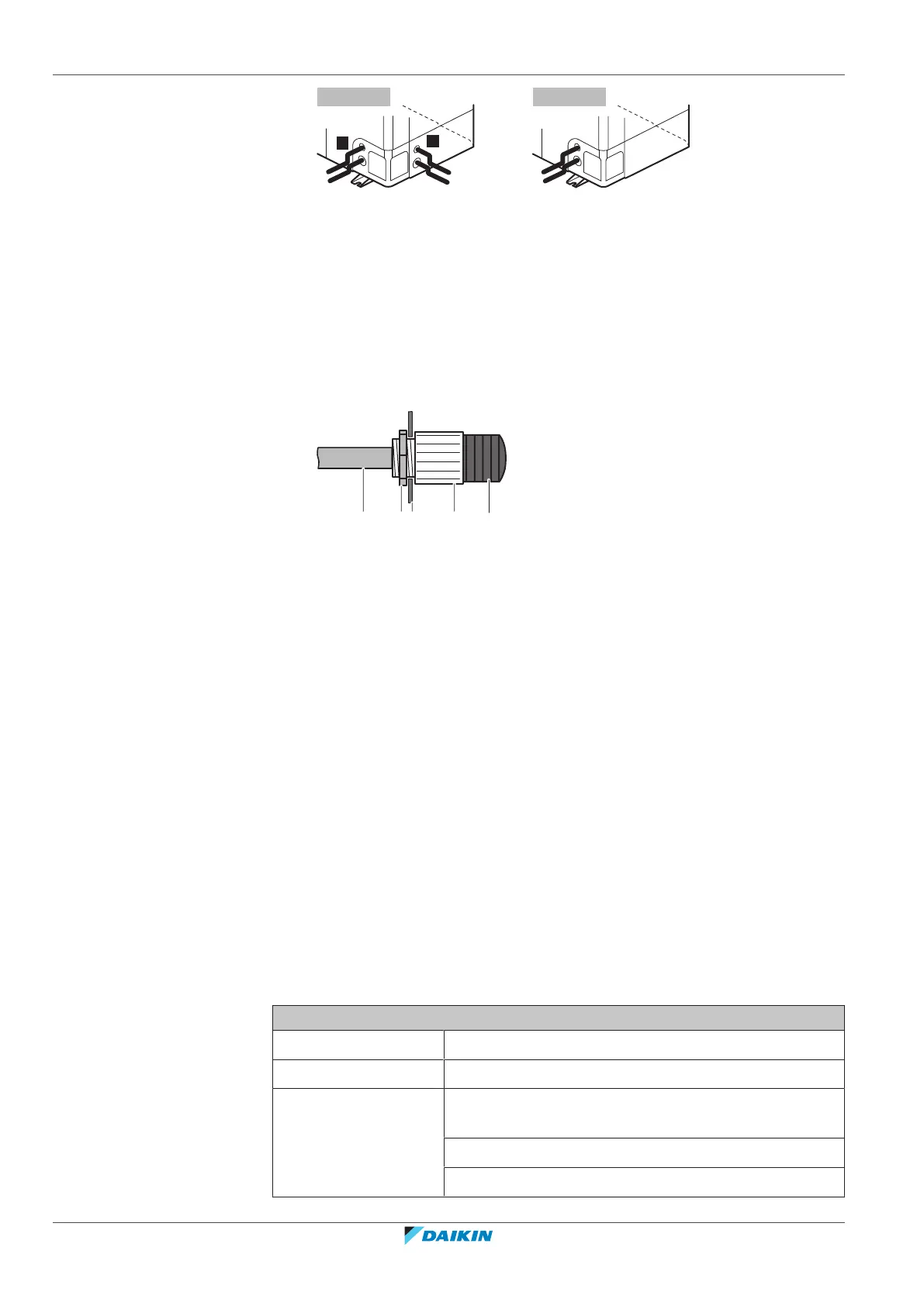
8 Install a cable protection in the knockout hole:
▪ It is recommended to install a PG type cable gland in the knockout hole.
▪ When you do not use a cable gland, protect the cables with vinyl tubes to
prevent the edge of the knockout hole from cutting the wires:
A Inside of the outdoor unit
B Outside of the outdoor unit
a Cable
b Bush
c Nut
d Frame
e Tube
9 Route the cables out of the unit.
10 Reattach the service cover. See "17.2.3To close the outdoor unit"[484].
11 Connect an earth leakage circuit breaker and fuse to the power supply line as
specified in "20.1.6Specifications of standard wiring components"[4123].
20.3 To connect the external outputs
SVS and SVEO output
The SVS and SVEO outputs are contacts on terminal X2M.
The SVS output is a contact on terminal X2M that closes in case a leak is detected,
failure or disconnection of the R32 sensor (located in the SV unit or indoor unit).
The SVEO output is a contact on terminal X2M that closes in case of occurrence of
general errors. See "10.1 Error codes: Overview" [4 43] and "25.3.1 Error codes:
Overview"[4160] for errors that will trigger this output.
Outdoor output connection requirements
Voltage 220~240V
Maximum current 0.5A
Wire size Only use harmonised wiring providing double insulation
and suitable for the applicable voltage.
2-core cable
Minimum cable section of 0.75mm²