20 | Electrical installation
Installer and user reference guide
127
RXYSA8~12AMY1B
VRV 5-S system air conditioner
4P752782-1A – 2024.02
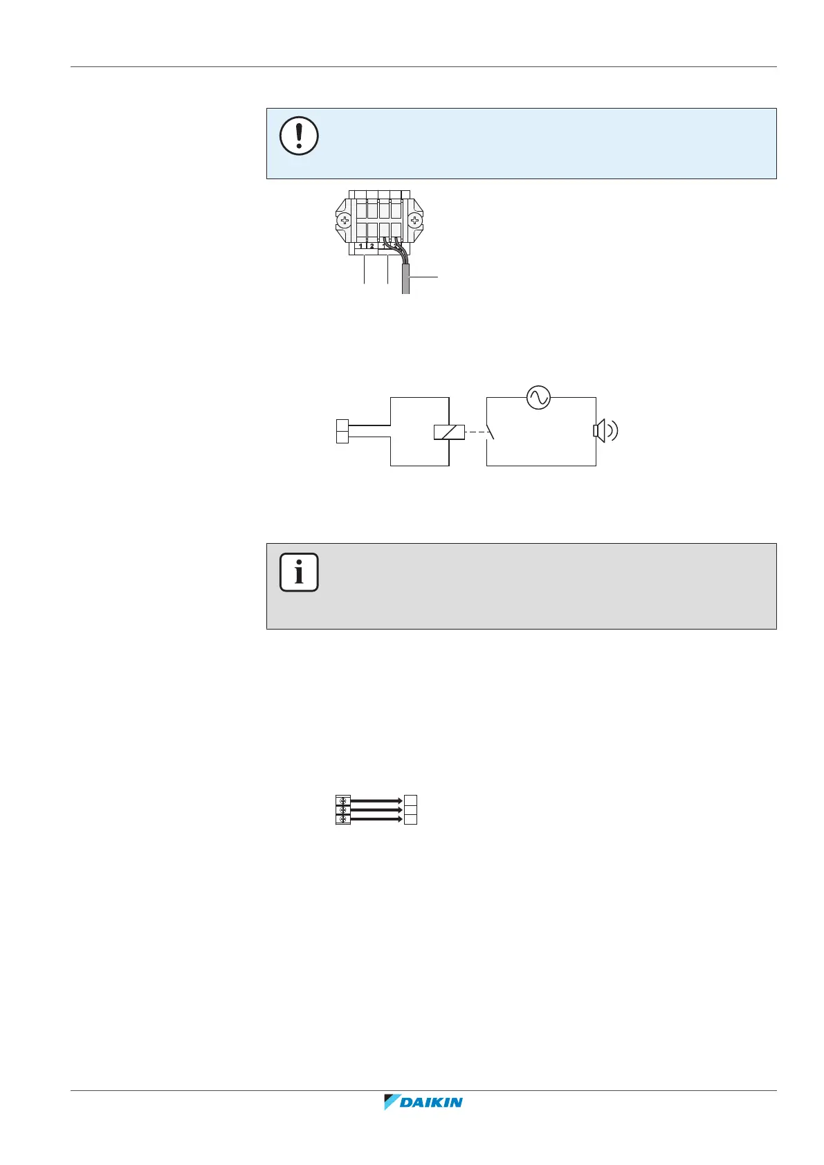
NOTICE
Do NOT use the outputs as a power source. Instead, use each output to energize a
relay that controls the external circuit.
a SVEO output terminals (1 and 2)
b SVS output terminals (1 and 2)
c Cable to SVS output device (example)
Example:
a SVS output terminal
b Relay
c AC power supply 220~240VAC
d External alarm
INFORMATION
Sound data about the refrigerant leakage alarm are available in the technical data
sheet of the user interface. E.g. the BRC1H52* controller generates an alarm of 65dB
(sound pressure, measured at 1m distance from the alarm).
20.4 To connect the cool/heat selector switch option
In order to control the cooling or heating operation from a central location, the
following optional cool/heat selector switch (KRC19-26A) can be connected:
1 Connect the cool/heat selector switch to terminal X1M of the cool/heat
selector PCB.
X1M Terminal on the PCB
KRC19-26A Cool/heat selector switch
2 Route the wires in the switchbox as shown: