28 Centrifugal Chillers IM 1044-2
Land wires on terminal strip TTB1
Control Wiring
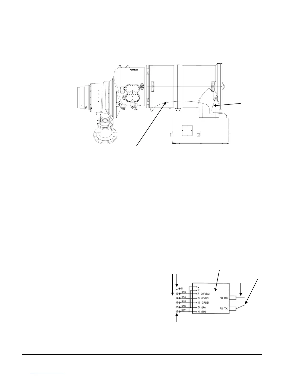
Power leads are brought in through a removable plate on the top of the terminal box (see Figure 15).
The terminal box power connectors are made to the landing points shown in Figure 15captive and
attached with a bolt already in the connector.
Figure 17, Control Wiring
Compressor to Terminal Box
Each sensor location cable has four wires connected to the motor by a M12 4-pin connector and to
the Thermistor Controller in the terminal box. Connections are as follows:
Front Temperature Sensors connect to the controller’s J2 terminal strip.
Brown---B1
White----B2
Blue------B3
Black-----Ground
Rear Temperature Sensors connect to the controller’s J6 terminal strip.
Brown---B6
White----B7
Blue------B8
Black-----Ground
Motor Terminal Box to Chiller Control Panel
Field wiring is required between the terminal box and
the chiller control panel to transmit motor information
to the chiller. Data from the compressor is sent to a
“Black Box” fiber isolator via a factory-wired fiber
optic cable (to isolate motor voltage from the chiller
controls). A cable is factory connected to terminals 33,
34, 35, and 36 on CTB1 in the chiller control box.
This cable is field installed into the motor terminal
box and wires in it connected to like terminal numbers
on terminal strip TTB1 located in the small lower box of
the motor terminal box.
Sensors Cable
Temperature
Sensors Cable
Factory
Wired
Factory Wired
Fiber Optic
Cables
FO “Black Box”
Isolator