IOM 1322 • WATER-COOLED SCROLL COMPRESSOR 84 www.DaikinApplied.com
When the Error is > the Valve Deadband setpoint, the valve
position analog output (% of full scale) is updated according to
the following equation.
New %Position = Old %Position + Increment/10
Valve Stage, controls from the fan stage setpoint in use. It is
recommended that the Valve Setpoint method explained above
be used rather than this mode.
This mode is only operational when the Valve/VFD Control
setpoint is set to Valve Stage. In this mode the valve output
is controlled as for Valve Setpoint mode (above), except that
the active setpoint for the controlled parameter is selected
according to the following table.
Active Setpoint
0 Valve Setpoint
1 Stage #1 ON
2 Stage #2 ON
3 Stage #3 ON
4 Stage #4 ON
VFD Stage, ValveSP/VFDStage, When the Valve/VFD Control
setpoint is set to None, Valve Setpoint, OR Valve Stage, this
output is set to 0. Otherwise, it will be controlled in a manner
identical to Valve Stage Mode (above) except that (1) it shall be
kept at zero until the rst fan stage is ON, and (2) the following
setpoints do not apply.
Valve Control Range (Min)
Valve Control Range (Max)
Valve Type
Valve Type settings are NC (normally closed to tower) or NO
(normally open).
These settings establish the operation of a tower bypass valve
(must be a 3-way valve).
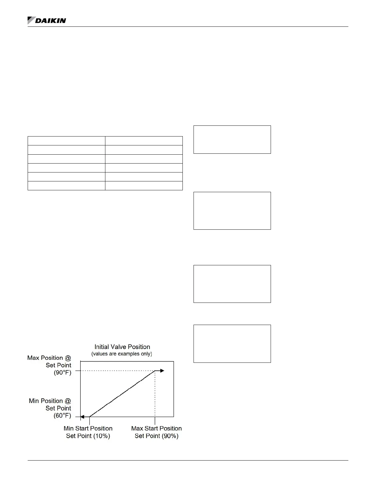
When the condenser pump is not in the RUN state, the valve
output shall be set as a function of entering condenser water
temperature (ECWT) per the following graph.
Figure 41: Initial Valve Position
Operation After Start
When the condenser pump is in the RUN state, the valve
output shall be controlled in one of two modes as specied
by the Valve/VFD Control setpoint. The controlled parameter
shall be the condenser entering water temperature. When the
desired output signal varies from 0 to 100%, the output voltage
shall vary as shown below.
0 to 10 VDC (Valve Type = NC)
10 to 0 VDC (Valve Type = NO)
SET TOWER SPs (5)
Valve SP is the minimum tower water temperature acceptable,
default is 65°F.
Valve DB is the dead-band in degrees, default is 2.0°F.
SET TOWER SPs (6)
The ValveStartposition is the position of the valve when the unit
starts. Default for minimum start position is 0%, and 100% for
maximum position.
SET TOWER SPs (7)
Defaults are 10% minimum and 90% maximum.
SET TOWER SPs (8)
PD Control Loop
Defaults are 25 for both error and slope.
TEST
The test screens are only available when the unit is in
TEST mode. Using these screens, any digital output can be
controlled manually.