Installation GuideDaintree
®
Networked Wireless Adapter (WA100-PM)
11
Figure 17: Emergency and Regular Light Fixtures: Wiring
to Dim while Regular Power is Available
Inthisapplication,theWA100-PMispoweredbytheRegular
powercircuitandisinstalledinsidetheRegularLightFixture.
While Regular power is supplied to the RRU-2 the WA100-PM
providesswitchedOn/OffpowertotheRegularLightFixture.
The WA100-PM also controls dimming to the Regular and
EmergencyLightFixture.The0-10Vdimmingcircuitfromthe
WA100-PMisbroughtintotheEmergencyLightFixture.The
EmergencyLightFixtureispoweredbytheEmergency
power circuit.
WhentheRRU-2senseslossofRegularpower,theRRU-2
disconnects the 0-10V output from the WA100-PM and the
EmergencyLightFixtureoperatesatmaximumoutputfromthe
Emergencypowercircuit.(Note:IftheRRU-2isnotinstalled,the
EmergencyFixturewilldimtominimumbecausetheWA100-PM
0-10V output shorts when the adapter loses power.)
7
Wiring Continued
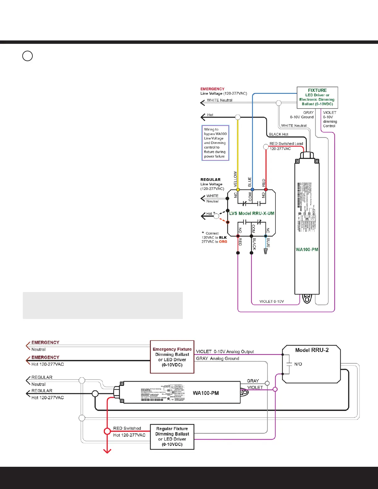
Set DIP switches and perform Installation Test appropriate
to 0-10v dimming and connected sensors.
Inthewiringdiagramhere,whileRegularpowerissuppliedtothe
LVSmodelRRU-X-UMtheWA100-PMprovidesswitchedOn/Off
powerand0-10Vdimmingcontroltothexturedriverorballast.
When the RRU-X-UM senses loss of Regular power it passes
Emergencypowerdirectlytothexture.Itdisconnectsthe
WA100-PM switched output and disconnects the WA100-PM
dimmingcontrolsothatthexturewilloperateatmaximum
output during the power failure.
Figure 16: Bypass WA100 switched power and 0-10V
dimming control during power failure
 Loading...