Installation GuideDaintree
®
Networked Wireless Adapter (WA100-PM)
2
2
4
3
WA100-PM Model Variants
DIP Switch Mode descriptions
DIP Switch settings
ThemodelnumberWA100wastheoriginalversionofthe
adapter and is no longer sold. The WA100-PM model monitors
and measures the power consumption of the connected lighting
load. The WA100-PM reports power measurement data to DCS.
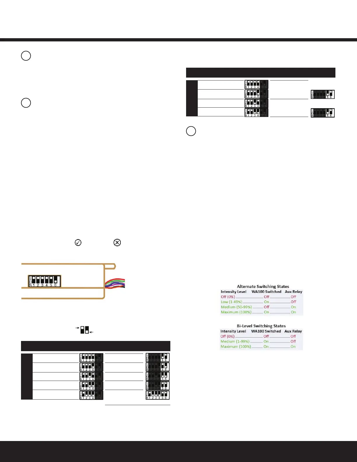
Figure 1: DIP switch location
Figure 2: DIP Switch Table — See DIP switch Mode
descriptions for information about each option.
DIPswitchsettingsenabletheWA100-PMtooperatea
ppropriately for the type of lighting control it provides and
the type of device(s) to which it is connected and adapting
forwirelesscommunication.SetDIPswitchesbasedonlyon
the devices that are physically wired to the WA100-PM.
There are two primary adaptation modes to choose from as
determinedbytheDIPswitch1setting.
• InLightAdapterMode,thesettingsareforthetype
oflightingcontrolthatisavailableontheconnected
driver,and/orthesensortype(s)connectedtothe
WA100-PM.
• IntheSwitchAdapterMode,settingsareforthe
connected switch type and whether the WA100-PM
is connected to a light.
CongureDIPswitchsettingsonlyasshowninthisinstruction.
Incorrect switch settings will cause unexpected operation.
AfteryouchangeDIPswitchsettings,youneedtopresstheblue
Resetbuttonfor3secondstoresettheunit.Releasethebutton
whenthegreenJoinedandredErrorLEDsbeginashing.
Light Adapter Mode
Control Type
On/Off + 0-10V dimming: providesOn/Offcontrolusingitsline
voltage Switched Load connection to the driver(s). It also provides
0-10V dimming control to the driver(s).
On/Off (no dimming): providesOn/Offcontrolusingitsline
voltageSwitchedLoadconnection,anditslowvoltagedigital
outputtoanexternalrelay.Note,bothoutputsareswitchedat
the same time in this driver control mode.
Alternate:providesOn/Offswitchingforonedriverloadusingits
linevoltageSwitchedLoadconnection,anditslowvoltagedigital
outputtoanexternalrelaytoswitchaseconddriverload.This
allowslightinglevelcontrolfornoload(0%),oneortheotherof
thetwoloads,andbothloads(100%).SeeFigure13.
Bi-Level:providesOn/Offswitchingforonedriverwithtwoloads
using its line voltage Switched Load connection and low voltage
digitaloutputanexternalrelaytoswitchthesecondload.This
allowslightingleveltocontrolfornoload(0%),partialload
(accordingtodrivercapability)orfullload(100%).SeeFigure12.
No Driver (sensors only): provides wireless adaptation to
connectedoccupancysensorand/orphotosensoronly.No
driver control.
Sensor
Toprovidewirelessadaptationforsensors,setDIPswitches1,5&
6 according to the type(s) of sensors connected to the WA100-PM.
Range Extender
TheWA100-PMjoinstheZigBeenetworkandactsonlyasa
wirelessrepeatertoimprovethewirelessrangeand/orreliability.
No lights or devices are connected to the WA100-PM.
Occupancy
Photosensor
Both
None
Range Extender*
nolight,nosensor
*Validonlywithrmwarev2.6orhigher
On/Off+0-10Vdimming
On/Off(nodimming)
Alternate Switching
Bi-Level
No Driver (sensors only)
SensorSwitches5&6Mode DriverTypeSwitches1to4
DIP Switch Positions
Light Adapter
OFF
ON
Light + Switch
(driver&switch
are same type)
No Light
(switch only)
Dimming
On/Off(nodimming)
Alternate Switch
Bi-Level
Light OutputSwitches5&6Mode Switch TypeSwitches1to4
Switch Adapter
Figure 2: DIP Switch Table — See DIP switch Mode
descriptions for information about each option.
 Loading...