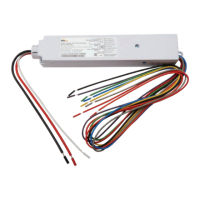
Installation GuideDaintree
®
Networked Wireless Adapter (WA100-PM)
3
5
6
7
Switch Adapter Mode
Occupancy Sensor Time Delays
Wiring
Switch Type
Dimming: operating the connected switch generates
dimmingandOn/Offsignals.
On/Off (no dimming): operating the connected switch
generatesOn/Offsignals.
Alternate: operating the connected switch will switch separate
drivers,providingnoload(0%),partialload(oneortheotherof
thetwoloads,accordingtothedriverloading)orfullload(100%).
Bi-Level: operating the connected switch will switch loads
independentlyinabi-leveldriver(or2drivers),providingno
load(0%),partialload(accordingtothedrivercapabilityor
driver loading) or full load (100%).
Light output ID
Light + Switch (driver and switch are the same type): the
connecteddrivermatchestheoperationalcapabilityofthe
switch.Forexample:
•IftheSwitchtypeis“Dimming,”adimmingswitchand0-10V
dimmabledriverarebothconnectedtotheWA100-PM.
See Figure 10.
•IftheSwitchtypeis“On/Off(nodimming)”anOn/Offswitch
isconnectedtotheWA100-PMdigitalinputandOn/Off
driver(s) are connected to the WA100-PM’s line voltage
SwitchedLoadconnectionand/oranexternalrelay
connected to the WA100-PM’s low voltage digital output.
•IftheSwitchtypeis“Bi-Level,”abi-leveldriverandbi-level
switch connect to the WA100-PM.
No Light (switch only): provides wireless adaptation for the
selected switch type only. No light is connected to the WA100-PM.
Occupancysensortimedelaysmustbesetforminimum.
WhentheDaintreeNetworkediscommissioned,timedelays
aresetintheDaintreeControlsSoftware(DCS)webapplication.
TheseDCS“Offdelays”startcountingdownafterthesensor’s
internaltimedelayexpires.Therefore,setoccupancysensorsfor
the minimum time delay during the WA100-PM installation.
Line voltage wiring connects to the electrical supply circuit and
tothedriver(s).TheBlack(Hot)yingleadandtheRed(Switched
Load)yingleadare14AWG.TheWhite(Neutral)yingleadis
18AWG.
Lowvoltage22AWGyingleadsprovideforconnectionsto
supply low voltage power and carry control signals to and
fromlowvoltagedevicessuchasswitches,dimmers,photocells,
isolated relays and 0-10V analog dimming driver controls. Do
not connect any single low voltage device to more than one
WA100-PM.
While the WA100-PM is in Installation Test mode the low voltage
devices connected to the WA100-PM directly control the lights
wiredtothesameWA100-PM.AfteryouexitInstallationTest
mode,thelightsturnOnandareNOTcontrolledbythedevices
connected to the WA100-PM.
Afterjoiningthewirelessnetwork,thecontrolsignalsfromthe
low voltage devices pass through the WA100-PM and are sent
wirelesslytotheDaintreeNetworked.Dependingonthezone
anddevicecongurationintheDCS,wirelesssignalsfromthe
WAC to the WA100-PM determine the operation of the light(s).
Design Caution
Wirelessadaptersmustalwaysbeprovidedwithuninterrupted
power. Do not install a wireless adapter such as the WA100-PM to
control an electrical circuit that provides power to other wireless
devices or adapters. If power to wireless adapters or devicesis shut
off,controlandcommunicationwiththemisdisabled.
Risk of electrical shock. Disconnectallpowerbeforeinstallationand
duringservicing.DonotopenWA100-PMenclosure;nouser-serviceable
parts inside. All installation and maintenance of line voltage equipment
mustbeperformedbyaqualiedelectrician.TheWA100-PMmustbe
installedinaccordancewithalllocal,state,andnationalelectricalcodes
andrequirements.Wiringconnectorsarenotsupplied.ULrecognized
wiringconnectorsmustbeusedintheinstallation.
CAUTION
Reducing noise on low voltage (0-10V) wiring
• Keep wiring as short as practical
• Keep signal lines separate from mains voltage lines.
• Reducetheareacreatedbythesignallinesand
theGNDreturn(i.e.,keepthemclosetogether).
• IfpossibletwistthesignallinewiththeGNDreturn.

 Loading...