EasyManua.ls Logo

Daintree GE Current WA100-PM - User Manual

Daintree GE Current WA100-PM
19 pages
Print Icon
To Next Page IconTo Next Page
Loading...
(WA100-PM)
Daintree
®
Wireless Adapter
BEFORE YOU BEGIN
Read these instructions completely and carefully.
Save these instructions for future use.
1
Installation Process
Installation Guide
WA100-PM
|
DT113
1. Disconnect power before installation. Turn off all power
toaffectedlightxturesbyturningoffcircuitbreakers.
Conrmthatpowerisoffatalllightxturesbefore
continuing installation.
2. Set the WA100-PM DIP switches to support the device(s)
beingconnectedtoit.SeeDIP Switch Settings (page 2).
3. IMPORTANT: Afxthesmalllabelwith4-5digitsofthe
WA100-PM’sIEEEaddressontheoorPlantoindicate
its location.
4. Mount the WA100-PM in the driver cavity of the light
xture,orexternaltothelightxture,ortoajunctionbox
approved for the application. See Mounting (page 12).
5. Connect low voltage wiring from the WA100-PM to the
driver,switch(es)and/orsensorsasappropriateforyour
application. See Wiring (pages 3-11). Cap any unused wires.
Risk of electrical shock.Disconnectpowerbeforeservicingor
installing product.
Install in accordance with National Electric Code and local codes.
WARNING
Risk of injury. Wear safety glasses and gloves during installation and
servicing.
CAUTION
The Daintree WA100-PM Wireless Adapter forms part of the
DaintreeNetworkedwirelesscontrolssolutionforsmart
commercialandindustrialbuildings.Ittransmitsandreceives
messages over the wireless ZigBee
®
networkandcontrolslights.
TheWA100-PMisanACpowereddevicethatprovidesOn/Off
switching as well as 0-10V analog dimming control for
LEDdriversandballasts.*Italsoprovidespowerforlowvoltage
occupancysensors,photosensors(daylightharvesters),
wallswitches,andcontrolsignalswhileitprovidesthewireless
adaptationthatenablesthemtocommunicatewiththe
rest of the wireless control solution. The control signals to and
fromtheseconnecteddevicespassbetweentheWA100-PM
and the Wireless Area Controller in Daintree Controls Software
(DCS)webapplication.
Error/Test — On when the Wireless Adapter is in an error state.
Flashes to indicate unit Reset and during Installation Test Mode (red).
Joined —OnwhentheWirelessAdapterhasjoinedaZigBee
®
network.
Flashes to indicate Reset and during sensor Installation Test Mode (green).
Power — On when power is applied to the Wireless Adapter (green).
LED Indicators
6. Connect line voltage wires from the supply circuit to the
WA100-PM and to the driver as shown in Wiring. Cap any
unused wire.
7.Checkloadcircuitsthenturnonthecircuitbreakerstopower
up the WA100-PM. The light connected to the WA100-PM turns
On when power is initially applied (and when power is restored
after a power failure).
8. Ensure the WA100-PM green Power LED is On.
9.PressandholdtheblueRESETbuttonontheWA100-PMfor
3secondstoresettheunit.Releasethebuttonwhenthegreen
JoinedLEDandtheredErrorLEDsbeginashing.
10. Perform the installation test appropriate for your application.
See Installation Tests(pages13-14)
Power
LED
Reset
Button
Joined
LED
Error
LED
Question and Answer IconNeed help?

Do you have a question about the Daintree GE Current WA100-PM and is the answer not in the manual?

Summary

Before You Begin

Safety Precautions

Essential safety guidelines including electrical shock and injury prevention.

Installation Process Overview

Initial Setup and Wiring

Covers power disconnection, DIP switches, IEEE address, and wiring connections.

Powering, Resetting, and Testing

Procedures for powering up, resetting the unit, and performing installation tests.

LED Indicators Explained

Understanding LED Status

Description of the Error/Test, Joined, and Power LEDs.

WA100-PM Model Variants

Model Overview

Details on the WA100-PM model features.

DIP Switch Settings

Configuration Modes and Functions

Explanation of Light Adapter and Switch Adapter modes and DIP switch functions.

Mode Descriptions

Details on Light Adapter and Switch Adapter mode options.

Sensor and Range Extender Modes

Configuration for sensors and use as a range extender.

Switch Adapter Mode

Switch Type and Light Output

Details on switch types, their functions, and light output matching.

Occupancy Sensor Time Delays

Minimum Delay Setting for DCS

Guidance on setting occupancy sensor time delays for commissioning.

Wiring Procedures and Cautions

Line and Low Voltage Wiring

Procedures for connecting line and low voltage wires.

Design Cautions and Noise Reduction

Important cautions and tips for reducing noise on low voltage wiring.

Wiring Diagrams

Wiring Identification and Dimming Fixtures

Diagrams for wire identification and dimming ballast/LED driver connection.

Wiring Diagrams

On;Off Fixtures and Occupancy Sensor Wiring

Diagrams for On/Off switching and occupancy sensor integration.

Wiring Diagrams

Dimming, Occupancy, and Photosensor Wiring

Diagrams for dimming, occupancy, and photosensor control.

Wiring Diagrams

Dimming, Sensor, and Switch Wiring

Diagrams for combined dimming, sensor, and switch configurations.

Wiring Diagrams

Bi-level and Alternate Switching Wiring

Diagrams for bi-level and alternate switching configurations.

Wiring Diagrams

Branch Circuit and 208 V Wiring

Diagrams for switching branch circuits and 208V wiring.

Wiring Diagrams

Switching Contactors Wiring

Wiring to control an external contactor.

Wiring Diagrams

Power Failure Bypass and Emergency Dimming Wiring

Diagrams for power failure bypass and emergency dimming.

Trimming and Dressing

Securing Low Voltage Wires

Instructions for tidying and securing unused low voltage wires.

Mounting Options

Fixture Mounting Methods

Describes mounting inside fixture, using bracket, or externally.

Bracket and External Mounting Diagrams

Diagrams for bracket and external mounting to fixtures.

Installation Tests

General Test Procedure and Notices

Overview of test mode, timing, and important notices like IEEE address recording.

Test Suite 1: Basic Driver Functions

Test procedure for On/Off, Dimming, Alternate, and Bi-Level drivers.

Test Suite 2: Driver with Occupancy Sensor

Test procedure for driver and occupancy sensor combination.

Installation Tests Continued

Switch, Sensor-Only, and Combined Tests

Tests for various switch, sensor, and combined sensor/driver operations.

Zigbee Network and Troubleshooting

Zigbee Network Joining

Procedure for joining the Zigbee lighting control network.

Troubleshooting Common Issues

Resolving installation test failures, sensor issues, and DIP switch errors.

Warning Messages

FCC and IC Compliance

Statements regarding FCC and Industry Canada compliance.

Plug Load Applications

Combination Plug Load and Light Wiring

Diagrams for controlling dimming and On/Off lights with plug loads.

Plug Load Applications Continued

Combination Plug Load with Input Control and Dimming Light

Wiring for plug load with input signal and dimming light.

Plug Load Applications Continued

Combination Plug Load with Input Control and On;Off Light

Wiring for plug load with input signal and On/Off light.

Specifications

Input, Output, and Low Voltage Details

Specifications for input voltage, output relay, low voltage, and radio properties.

Operating Environment and Compliance

Details on operating environment, dimensions, and certifications.

Caution: Battery Replacement

Warning regarding incorrect battery type and disposal.

Overview

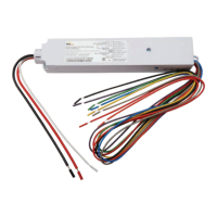
The Daintree WA100-PM Wireless Adapter is a key component of the Daintree Networked wireless controls solution, designed for smart commercial and industrial buildings. It facilitates wireless communication via the ZigBee® network, transmitting and receiving messages to control lighting.

Function Description:

The WA100-PM is an AC-powered device that offers On/Off switching and 0-10V analog dimming control for LED drivers and ballasts. It also supplies low-voltage power for various devices such as occupancy sensors, photosensors (daylight harvesters), and wall switches, while providing the wireless adaptation necessary for these devices to communicate with the broader wireless control solution. Control signals from connected devices pass through the WA100-PM to the Wireless Area Controller, managed via the Daintree Controls Software (DCS) web application. The device monitors and measures the power consumption of the connected lighting load, reporting this data to DCS.

Important Technical Specifications:

  • Input Voltage: 120-277VAC, 50-60Hz.
  • Switched Output Relay: 15A for driver/incandescent loads at 120-277VAC, 1hp at 120-230VAC (switched to Hot/Active).
  • Low Voltage Output: 24VDC; 75mA maximum.
  • Low Voltage Wiring: 22AWG, 600V, UL 1015, plenum rated. Maximum recommended length of up to 100' (30m).
  • Analog Dimming: 0-10VDC, 5mA max (sink or source), up to 10 typical 0.5mA sinking drivers/ballasts.
  • Analog Input: Photosensor 0-10VDC.
  • Digital Input (2): Active high. Supports occupancy sensor and Dim Up/Down (switch mode).
  • Digital Output: LSD (low side driver) aux relay control, 75mA maximum (including attached sensors).
  • Radio Properties: 2.4 GHz, +8 dBm. Range is dependent on RF propagation variables such as metal obstacles.
  • Operating Environment: Indoor, dry location; -4° to 149°F (-20° to 65°C).
  • Compliance: CSA certified, plenum rated, FCC Part 15, CA IC.
  • Dimensions: 9.4" L x 1.7" W x 1.18" H (10.1" L x 1.7" W x 1.18" H with mounting bracket).
  • Processor: Intel® Atom™ Processor E3805.

Usage Features:

The WA100-PM's operation is configured via DIP switches, which determine the type of lighting control provided and the connected device(s). There are two primary adaptation modes: Light Adapter Mode (for lighting control type and sensor types) and Switch Adapter Mode (for switch type and light connection).

  • Light Adapter Mode:
    • On/Off + 0-10V dimming: Provides both On/Off and 0-10V dimming control.
    • On/Off (no dimming): Provides On/Off control using line voltage Switched Load and low voltage digital output for an external relay.
    • Alternate: Switches separate drivers, providing 0%, partial, or full load control.
    • Bi-Level: Controls two loads independently, allowing 0%, partial, or full load.
    • No Driver (sensors only): Adapts for occupancy sensors and/or photosensors without driver control.
    • Range Extender: Acts as a wireless repeater to improve network range/reliability (requires firmware v2.6 or higher).
  • Switch Adapter Mode:
    • Dimming: Switch generates dimming and On/Off signals.
    • On/Off (no dimming): Switch generates On/Off signals.
    • Alternate: Switch controls separate drivers for 0%, partial, or full load.
    • Bi-Level: Switch controls loads independently in a bi-level driver.
    • Light Output ID: Configures the WA100-PM based on whether a driver and switch are of the same type (e.g., dimming switch with 0-10V dimmable driver).
    • No Light (switch only): Provides wireless adaptation for the selected switch type without a connected light.
  • Occupancy Sensor Time Delays: Occupancy sensors should be set for minimum time delay during installation, as "Off delays" are configured in the DCS web application.
  • Wiring: Line voltage wiring (Black Hot 14AWG, Red Switched Load 14AWG, White Neutral 18AWG) connects to the electrical supply and driver(s). Low voltage wiring (22AWG) connects to devices like switches, dimmers, and sensors. It is crucial not to connect any single low voltage device to more than one WA100-PM.
  • Installation Test Mode: During this mode, low voltage devices directly control the lights. After exiting, lights are controlled by the Daintree Networked system based on DCS configurations.
  • Power Failure Bypass: The WA100-PM can be wired to bypass switched power and 0-10V dimming control during a power failure, allowing the fixture to operate at maximum output.

Maintenance Features:

  • Installation Process: Includes steps for disconnecting power, setting DIP switches, affixing IEEE address labels, mounting, and connecting low-voltage and line-voltage wiring.
  • Reset Functionality: A blue RESET button allows for unit reset (3-second press), indicated by flashing green Joined and red Error LEDs.
  • LED Indicators:
    • Error/Test (red): On for error state, flashes for unit reset and during Installation Test Mode.
    • Joined (green): On when joined to a ZigBee® network, flashes for reset and during sensor Installation Test Mode.
    • Power (green): On when power is applied.
  • Troubleshooting: Provides guidance for failed installation tests (confirming power, connections, DIP switch settings), issues with occupancy sensor tests (checking sensor detection and time delay), and invalid DIP switch configurations (red Error LED flashing).
  • Wiring Best Practices: Recommendations for reducing noise on low voltage wiring include keeping wires short, separating signal lines from mains voltage, reducing the area created by signal lines and GND return, and twisting signal lines with GND return.
  • Trimming and Dressing: Instructions for securing unused low voltage wires by cutting, isolating ends with wire nuts/shrink tubing, and wrapping them around the adapter.
  • Mounting: The WA100-PM can be mounted in a driver cavity, externally to a junction box, or using the included mounting bracket, which offers a screw-mounting alternative and a slot for wires. A barcode label with the full IEEE address should be affixed to the outside of the fixture for easy identification.

Daintree GE Current WA100-PM Specifications

General IconGeneral
BrandDaintree
ModelGE Current WA100-PM
CategoryAdapter
LanguageEnglish