(WFA100-SN)
Daintree
®
Wireless
Fixture Adapter
BEFORE YOU BEGIN
Read these instructions completely and carefully.
Save these instructions for future use.
1
Installation Process
Installation Guide
WFA100-SN
|
DT111
1. Disconnect power before installation. Turn off all power
toaffectedlightxturesbyturningoffcircuitbreakers.
Conrmthatpowerisoffatalllightxturesbefore
continuing installation.
2. IMPORTANT: UsetheprovidedFixtureandPlanlabelsto
identifythewireless-adaptedxturelocation.AttachtheFixture
labeltotheoutsideofthexture.AttachthePlanlabelatthe
xturelocationonthefacilityoorplan.
4.ConnectlowvoltagewiringfromtheWFA100-SNtotheballast,
and sensors as appropriate for your application. See Wiring
(pages 2-7).
5. Connect line voltage wiring from the supply circuit to the
WFA100-SNandfromtheWFA100-SNtotheballast.
See Wiring.
Risk of electrical shock.Disconnectpowerbeforeservicingor
installing product.
Install in accordance with National Electric Code and local codes.
WARNING
Risk of injury. Wear safety glasses and gloves during installation and
servicing.
CAUTION
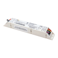
The Daintree Wireless Fixture Adapter (WFA100-SN)
formspartofDaintreeNetworkedincommercialandindustrial
buildings.Ittransmitsandreceivesmessagesoverthewireless
ZigBee
®
networkandcontrolslights.
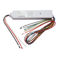
FixtureadaptersareACpowereddevicesthatprovideOn/Off
switchingaswellas0-10Vanalogdimmingcontrolforballasts
and LED drivers. The WFA100-SN also provides power and signal
connections for low voltage occupancy sensors and photosensors
(daylightharvesters).TheWFA100-SNautomaticallycongures
itself for the type of sensor(s) connected to it.
TheWFA100-SNprovidesthewirelessadaptationthatenables
connected devices to communicate with the rest of the
wireless lighting control solution. The adapter also serves as
acommunicationrouterintheZigBeewirelessmeshnetwork.
ControlsignalspassbetweentheadapterandtheWireless
AreaControllerintheDaintreeNetworkedplatform.
Figure 1: LED Indicators
Power
LED
Joined
LED
Error
LED
Error/Test — On when the Wireless Adapter is in an error state.
Flashes to indicate unit Reset and during Installation Test Mode (red).
Joined — On when the Wireless Adapter has joined a ZigBee
®
network.
Flashes to indicate Reset and during sensor Installation Test Mode (green).
Power — On when power is applied to the Wireless Adapter (green).
LED Indicators
6.Checkloadcircuitsthenturnonthecircuitbreakerstopower
up the WFA100-SN. The light connected to the WFA100-SN
turns On when power is initially applied (and when power is
restored after a power failure).
7.EnsuretheWFA100-SNgreenPowerLEDisOn.
8.PressandholdtheResetbuttonontheWFA100-SNfor
3secondstoresetit.Releasethebuttonwhenthegreen
JoinedLEDandtheredErrorLEDsbeginashing.
9.Performtheinstallationtestappropriateforyourapplication.
See Installation Tests (pages 9-10).