Installation GuideDaintree
®
Networked Wireless Fixture Adapter (WFA100-SN)
7
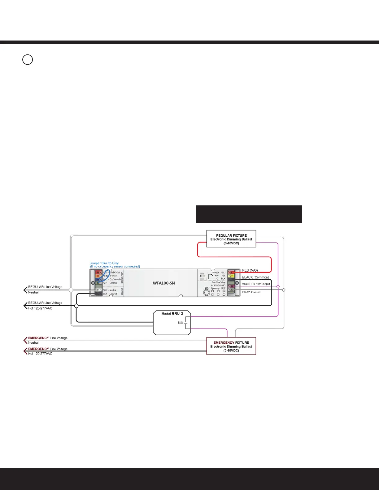
Figure 11: Emergency Fixture and Regular Fixture: Wiring to Dim while Regular Power is Available
3
Wiring Continued
Inthewiringdiagrambelow,theWFA100-SNispoweredbythe
RegularpowercircuitandisinstalledinsidetheRegularFixture.
WhileRegularpowerissuppliedtotheRRU-2,theWFA100-SN
providesswitchedOn/OffpowertotheRegularFixtureballast.
TheWFA100-SNalsocontrolsdimmingtotheRegularFixture
andtheEmergencyFixture.TheEmergencyFixtureispowered
bytheEmergencypowercircuit.
The0-10VdimmingcircuitfromtheWFA100-SNisbrought
intotheEmergencyFixture.
WhentheRRU-2senseslossofRegularpower,theRRU-2
disconnects the 0-10V output from the WFA100-SN and the
ballastwilloperateatmaximumoutputfromtheEmergency
powercircuit.(IftheRRU-2isnotinstalled,theEmergency
FixturewilldimtominimumbecausetheWFA100-SN0-10V
output shorts when the adapter loses power.)
Perform Installation Test
appropriate to connected sensors