23
Fahrzeug-/Funktionsdecoder ab Firmware-Version 1.11
23
Locomotive/Vehicle function decoder from firmware version 3.12
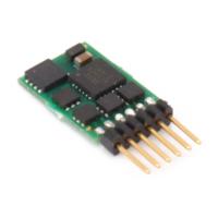
DH21B-5
21 pin interface
1 22
2 21
3 20
4 19
5 18
6 17
7 16
8 15
9 14
10 13
11 12
GPIO
*) AUX7
*) AUX6
*) AUX4
ZCLK
ZDAT
LR
LV
--
--
Index
G1
G2
GND
M1
M2
AUX5 *)
VS
AUX1
AUX2
AUX3 *)
VCC
M1, M2 .............. Motor connection 1, 2
G1, G2 ............... Track connection 1, 2
LV, LR ................ Front light, rear light (each 150 mA)
AUX1, AUX2 ..... Additional function 1, 2 (each 300 mA)
AUX3 ... AUX7 ..Unamplified function *)
VS ...................... Supply voltage
ZVS ................... SUSI supply voltage
ZCLK .................. SUSI clock
ZDAT ................. SUSI data
GND .................. Ground (0 V)
GPIO .................. General input / output (max. +5 V / max. 3 mA)
or AUX8 unamplified *)
VCC
...................+5 V / max. 15 mA
*) Unamplified function outputs: See supplement 3.
If necessary: Connect blue wire (common return conductor) to VS.
You can connect a buffer capacitor to ZVS (+) and GND (-).
 Loading...