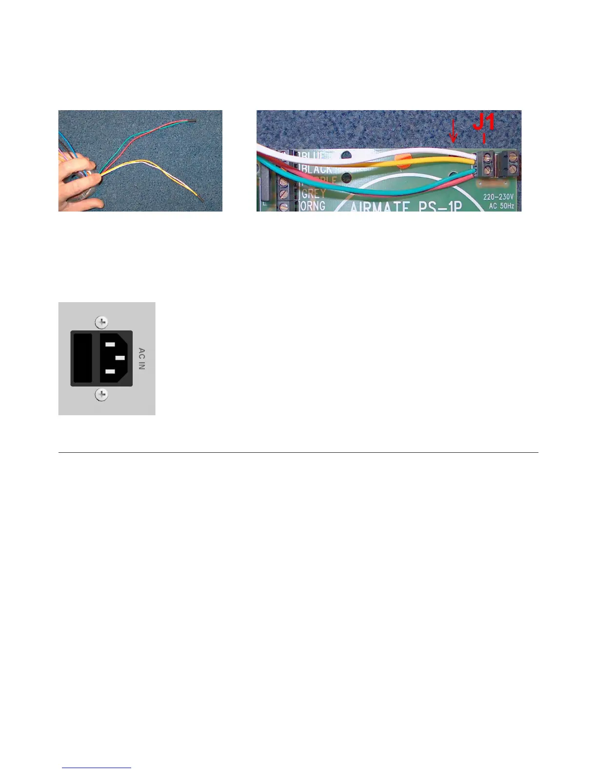
Step 1: Rerouting the power-cabling.
Twist the Green and the Red wire together.
Twist the White and the Yellow together.
Then connect both wires to the connector J1 as pictured.
The red indicator (arrow) species the point ( 2 holes) where the wires need to be mounted to the Print Circuit
Board with a tie-wrap.
Step 2: Replacing the fuse.
The fuse-box is integrated in the AC socket. The fuse must be replaced from a 0.5A to a 1A.
Make sure the 230V marking on the fuse-holder is on TOP!!! Else the device will not function.
17. ELECTROMAGNETIC COMPATIBILTY
This unit conforms to the Product Specications noted on the Declaration of Conformity.
Operation is subject to the following two conditions:
• This device may not cause harmful interference
• This device must accept any interference received, including interference that may cause unde-
sired operation
• Operation of this unit within signicant electromagnetic elds should be avoided
• Use only shielded interconnecting cables.