© Danfoss A/S (AC-MCI/MWA), 2012-05 DKRCI.PD.SC0.C3.02 / 520H5687 5
Liquid Level Sensor, AKS 4100/4100U
Measuring principle
(Cable and Coaxial)
The AKS 4100/4100U electronic converter emits
low-intensity, high frequency electromagnetic
pulses with a width of approximately 1
nanosecond, which travel at the speed of light
along the probe (wire or coaxial cable) down to the
liquid surface.
The pulses are reected by the liquid surface,
guided back along the probe, and received and
analysed by the AKS 4100/4100U electronic
converter and then converted into a liquid level
reading. This method is called time domain
reectometry (TDR) or guided microwave.
The dielectric constant, εr, of the liquid is a key
parameter and has a direct impact on the degree
of reection of the high frequency electromagnetic
pulses. Liquids with high εr values, such as ammonia,
produce strong reections, while liquids with low
εr values, such as CO
2
, produce weak reections.
As long as the εr value of the liquid refrigerant is
higher than 1.2, AKS 4100/4100U can detect the
liquid level and level measurement accuracy is not
aected.
If the temperature condition in the standpipe/
vessel is known, a constant (dielectric constant
of the refrigerant gas) can be entered (parameter
2.5.3 GAS EPS.R), in order to obtain improved Top
and Bottom Dead Zone values.
Refer to pages 7 to 8 for Measuring range of AKS
4100/4100U - CABLE version and COAXIAL version.
For details of gas constant values for dierent
temperatures and refrigerants plus the procedure
for entering these via the HMI, refer to pages 13 to 16.
Main technical data
(see a complete list of all
technical data on page 11)
Supply Voltage
14-30 V d.c. Min/Max. Value for an output of 22 mA
at the terminal.
Ambient temperature supply voltage limitations:
-40°C/+80°C(–40°F / +176°F) : 16-30 V d.c.
-20°C/+80°C(–4°F / +176°F) : 14-30 V d.c.
Load
RL [Ω] ≤ ((Uext -14 V)/20 mA).
– Default (Error output set to 3.6 mA)
RL [Ω] ≤ ((Uext -14 V)/22 mA).
– (Error output set to 22 mA)
Cable gland
AKS 4100 PG 13, M20×1.5 ;
(cable diameter: 6-8 mm (0.24-0.31in.)
AKS 4100U ½ in. NPT
Refrigerant temperature
–60°C/100°C (–76°F/212°F)
Ambient temperature
–40°C / +80°C (–40°F / +176°F)
For HMI : –20°C / +60°C (–4°F / +140°F)
Process pressure
–1 barg / 100 barg (–14.5 psig / 1450 psig)
Terminals (spring loaded)
0.5-1.5 mm² (~20-15 AWG)
Enclosure:
IP 66/67 (~NEMA type 4X)
Mechanical connection
Cable version/Coaxial version:
AKS 4100: G1 in. pipe thread.
Aluminium gasket included
AKS 4100U: ¾ in. NPT
Refrigerants
The listed refrigerants are qualied and approved by
Danfoss
R717 / NH
3
–40°C / +50°C (–40°F / +122°F)
R744 / CO
2
–50°C / +15°C (–58°F / +59°F)
HCFC: R22 –50°C / +48°C (–58°F / +118°F)
HFC: R404A –50°C/ +15°C (–58°F / +59°F)
R410A –50°C /+15°C (–58°F / +59°F)
R134A –40°C /+50°C (–40°F /+122°F)
The listed refrigerants may be used in the complete
temperature range of AKS 4100/4100U, however,
the accuracy may be aected if the above listed
temperature range is exceeded.
Other refrigerants within the groups of HCFC and
HFC can be detected and measured if the following
conditions are fullled:
Reference conditions
Dielectric constant
Cable version to be used in R717 / NH
3
, HCFC and HFC
εr, liquid > 5.6
The coaxial version is mandatory for R744 / CO
2
εr, liquid > 1.3 and marine applications.
The coaxial version can also be used in
R717 / NH
3
, HCFC and HFC.
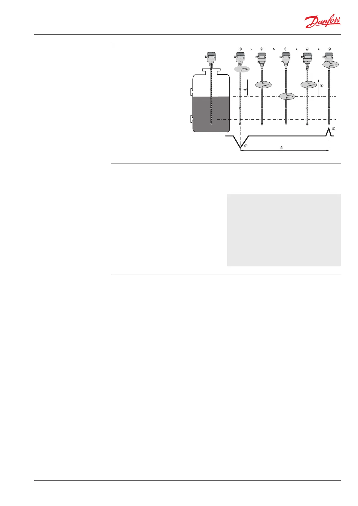
1. The electromagnetic (EM) pulse is
transmitted by the signal converter
2. The pulse goes down the probe
at the speed of light in air, V1
3. The pulse is reected
4. The pulse goes up the probe at
speed, V1
5. The converter receives the pulse
and records the signal
6. The EM pulse moves at speed, V1
7. Transmitted EM pulse
8. Half of this time is equivalent
to the distance from the
reference point of the device
(the ange facing) to the surface
of the product
9. Received EM pulse
 Loading...