VLT
®
5000/5000 Flux/6000 HVAC/8000 AQUA PROFIBUS
MG.90.D1.02 – VLT is a registered Danfoss trademark
11
■ Timing
■ VLT response time behaviour
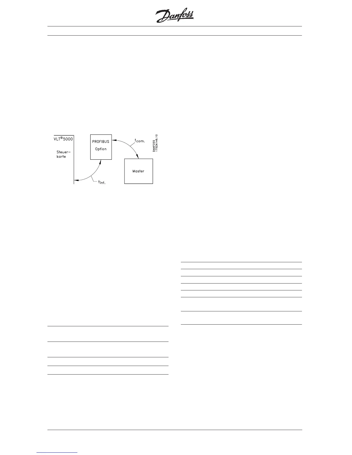
The period for the update through the PROFIBUS
connection can be subdivided into two portions:
1) The communication period, i.e. the time required
to transmit data from the master to the slave
(VLT with PROFIBUS option), and
2) the internal update period, i.e. the time required
to transmit data between the VLT control card
and the PROFIBUS option card.
The communication period (t
com
) depends on the
respective transmission speed (baud rate) and the
type of master being used. The shortest achievable
communication period is approximately 30 µsec
per slave with the VLT PROFIBUS option when DP
communication with a data quantity of 4 bytes (PPO
type 3) at 12 Mbaud is used. The communication
period increases with more data or lower
transmission speeds.
The internal update period (t
int
) depends on the
respective data as there are different channels for
the transmission of data, with time-critical data,
such as the control word, being given the highest
priority. The internal update time for the respective
data types is listed below.
Update
Data time, t
int
Control word/main reference value
(Part of PPO) 2 msec.
Status word/respective output frequency
(Part of PPO) 2 msec.
Read parameter through PCD portion of PPO
Write parameter through PCD portion of PPO
Timing
■ Time behaviour during system update
The system update period is the time required to
update all slaves of the network when cyclical
communication is used.
The update time of a single slave is composed of
both the communication period (depending on the
baud rate) and the station delay (TSDR) in the
slave, and of the delay in the master associated
with the station.
The station delay (TSDR) is the delay time from the
moment when a station receives the last bit of a
telegram to the moment when it sends the first bit
of the next telegram. The station delay is defined
by two parameters: the minimum station delay
(TSDR
min
) and the maximum station delay (TSDR
max
).
Current station delay for the VLT PROFIBUS option:
– DP: 11 bit times
Current master station delay:
– This information must be provided by the manu-
facturer of the respective PROFIBUS master.
Example
– DP master with 1.5 MBaud and PPO type 3
(4 byte data); the assumption here is for 50 bit
times as master TSDR.
Time [msec] Action
0 Master starts data transmission
Last bit received in slave
Slave station delay
Slave starts data transmission
Last bit received in master
Master station delay
(50 bit times » 0.033)
Master ready for data transmission
to next slave
 Loading...