AQ13418645844301-010402 6 | © Danfoss | 2021.05
AFD/VFG(S) 2(1)
ENGLISH
Safety Notes
Prior to assembly and commissioning
to avoid injury of persons and
damages of the devices, it is
absolutely necessary to carefully read and
observe these instructions.
Necessary assembly, start-up, and maintenance
work must be performed only by qualified,
trained and authorized personnel.
Prior to assembly and maintenance work on the
controller, the system must be:
- depressurized,
- cooled down,
- emptied and
- cleaned.
Please comply with the instructions of the
system manufacturer or system operator.
Definition of Application
The controller is used for pressure reduction
of steam, water and water glycol mixtures for
heating, district heating and cooling systems.
The technical data on the label plates determine
the use.
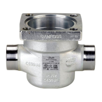
Scope of Delivery ❶
- control valve VFG 2(1)/VFGS2
- extension piece ZF4 for DN < 150
if T
max
> 200 °C
- actuator AFD
- flow divider FD for steam noise reduction
- seal pot V1, V2 if T > 150 °C
- impulse tubes AF
Mounting
Only for VFGS 2 valves:
If ordered, install flow divider cage.
Read installation Instructions ❷
attached to the flow divider cage.
Admissible Installation Positions ❸
DN 15-80 media temperatures up to 120 °C:
Can be installed in any position.
DN 100-250 and DN 15-80, media
temperatures higher >120 °C and always at
steam:
Installation only permitted in horizontal
pipelines with the actuator hanging
downwards.
Installation Scheme ❹
Note:The valve is open without pressure and
is closing on rising pressure.
System must be protected behind the
pressure reducer by a safety
monitoring unit (SV, SÜV) ①.
Valve Installation ❺
1. Install strainer ❹ ② before the controller.
2. Rinse system prior to installing the valve.
3. Observe flow direction ③ on the valve body.
Flanges ④ in the pipeline must be in
parallel position and sealing surfaces
must be clean and without any
damage.
4. Install the valve.
5. Tighten screws crosswise in 3 steps up to the
max. torque.
Valve Actuator Installation ➏
Only for valves
VFGS2 DN 15-125; T = 200-350 °C:
Install stem extension ZF4.
Read Installation Instructions attached to the
stem extension ①.
Valves DN 150‑250
The actuator stem must be screwed
into the valve stem.
Observe the Installation Instructions for the DN
150 - 250 valves ②.
1. Place the actuator stem to the valve stem
and screw together gently by hand until it
stops. Rotate the nut simultaneously - makes
it easier ③.
2. Unscrew for approximately one turn.
3. Tighten union nut ④
Torque 100 Nm
Valves DN 15‑125
1. Screw the actuator nut to the valve neck ③.
2. Align actuator, observe position of impulse
tube connection ⑤.
3. Tighten union nut ④
Torque 100 Nm
Impulse Tube Installation ➐
Note: When installing seal pots ①, please
observe the Installation Instructions for the
seal pots.
Which impulse tubes to use?
Use the impulse tube set AF (1×) ②:
Order No.: 003G1391
or use the following pipes:
Stainless steel Ø 10×0.8
DIN 17458
DIN 2391
Steel Ø 10×1 DIN 2391
Copper Ø 10×1 DIN 1754
The impulse tube ③ can be connected directly
to the valve ④ or to the pipeline ⑤.
⑥ ventilation socket, do not connect
impulse tube.
Connection to the valve ❽
1. Remove plug ① at the valve (return side).
2. Screw in threaded joint G ⁄ ② with copper
seal, Torque 40 Nm.
- or -
Connection to the Pipeline ➒ ④
No connection downwards/upwards ⑤, could
bring dirt/air into an impulse tube.
1. Cut pipe in rectangular sections ⑥ and
deburr.
2. For copper pipe:
insert sockets ⑦ on both sides.
3. Verify the correct position of the cutting
ring ⑧.
4. Press impulse tube ⑨ into the threaded joint
up to its stop.
5. Tighten union nut ⑩ Torque 40 Nm.
Insulation ❿
For media temperatures up to 100 °C the
pressure actuator ① may be insulated.
Dismounting ⓫
Danger
Danger of injury by steam, hot
water!
Valve without actuator is open ①, seal ② is in
the actuator.
Prior to dismounting, depressurize system!
Carry out dismounting in reverse order to
mounting.
Leak and Pressure Tests ⓬
Observe max. permitted pressure, see
below.
The pressure ② behind the valve must not
exceed the pressure ① before the valve.
Non compliance may cause damages at the
controller ③.
Prior the pressure tests, it is absolutely
necessary to disconnect the impulse tube ④.
Close connections with a plug e.g. G ⁄ ISO 228.
Max. pressure [bar] with connected impulse
tube
2
Observe nominal pressure ⑤ of the valve.
Max. test pressure is 1.5 × PN.
Filling the System, First Start‑up ⓭
The pressure ② behind the valve must
not exceed the pressure ① before the
valve.
Non-compliance may cause damages at the
controller ③.
1. Open shut-off units ④ at the impulse tube, if
any.
2. Slowly open shut-off unit ⑤ (inlet).
3. Slowly open shut-off unit ⑥ (outlet).
4. Only for actuator 630 cm²:
Open ventilation screw ⑦ by about 2 turns.
As soon as water is penetrating, close screw.
Putting out of Operation ⓮
1. Slowly close shut-off units ① (inlet).
2. Slowly close shut-off units ② (outlet).
Setpoint Adjustment ⓯
Set-point range see rating plate ①.
1. Adjust flow rate at a fitting ② after the
pressure reducer ③ to about 50 % of the
max. flow rate ④.
2. Adjustment of the pressure behind the
valve ⑤.
Turning to the right ⑥ increases the
set-point (stressing the spring, tension
spring)
Turning to the left ⑦ reduces the set-point
(unstressing the spring)
3. The set-point adjuster ⑧ may be sealed.
Dimensions, Weights ⓰
 Loading...