Do you have a question about the Danfoss AK-CC 250A and is the answer not in the manual?
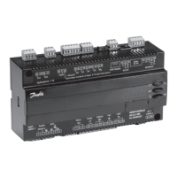
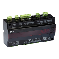
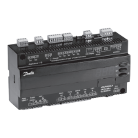
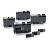
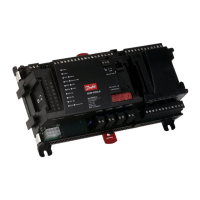
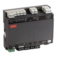
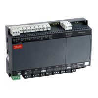
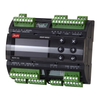
Identifies the AK-CC 250A model and its primary electrical and environmental specifications.
Details the functionality and load capacities of the device's output relays (DO1-DO4).
Overview of supported sensors (Pt/PTC) and the MOD-BUS communication interface.
Explains coordinated defrost and data communication via MOD-BUS.
Comprehensive set of electrical wiring diagrams for various device configurations.
Step-by-step guide for configuring the device's operational parameters.
Detailed list of all configurable parameters, their codes, and default/actual values.
Configuration options for fan operation, HACCP function, and real-time clock settings.
Settings for various other device parameters not categorized elsewhere.
Guide to operating the device using its buttons and interface for parameter access.
List and explanation of device fault and alarm codes for troubleshooting purposes.
Explanation of the LED indicators on the device for operational status.
Details on sensor types, their resistance values, and compatibility with the controller.
| Model | AK-CC 250A |
|---|---|
| Type | Controller |
| Power Supply | 24 V AC/DC |
| Display Type | LCD |
| Communication Protocol | Modbus RTU |
| Analog Inputs | 2 |
| Relay Outputs | 3 |
| Power Consumption | 5 W |
| Enclosure | Plastic |
| Protection Class | IP20 |
| Weight | 0.3 kg |



 Loading...