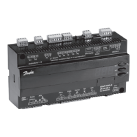
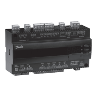
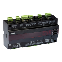
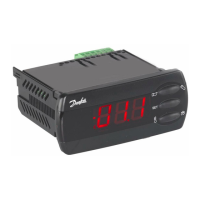
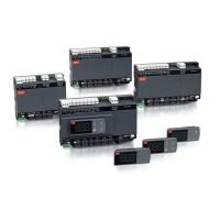
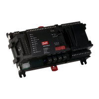
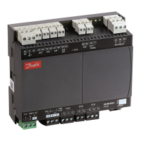
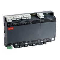
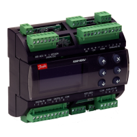
Do you have a question about the Danfoss AK-CC 550 and is the answer not in the manual?
Provides an overview of the controller's application capabilities and flexibility.
Details usage for standard appliances with one valve, one evaporator, and one section.
Covers applications with two evaporators or two refrigeration sections.
Explains control of liquid injection and temperature using various methods.
Details alarm monitoring using S3 and S4 sensors with adjustable limits.
Covers thermostat bands, appliance cleaning, and alarm monitoring.
Explains defrost types, sequences, start, and stop controls.
Details coordinated defrost, defrost on demand, and melting functions.
Manages the operation of two compressors for optimal capacity and runtime.
Covers rail heat, fan pulse control, and light/night blind functions.
Details digital input functions, door contact, and forced closing.
Explains heating function, data communication, and display options.
Provides an overview of applications and specific wiring diagrams for 1-10.
Details controller functions, parameters, and thermostat settings.
Covers alarm limits, delays, and melt function parameters.
Explains settings for compressor running times and staging.
Details parameters for defrost methods, stop temps, and intervals.
Covers drip-off time, fan delay, defrost sensor, and adaptive defrost settings.
Details fan control settings and real-time clock configuration.
Covers output delay, digital inputs, network address, and application selection.
Explains DI3 input, rail heat control, and light/night blind settings.
Lists and explains status codes shown on the controller display.
Provides a reference for alarm codes and their descriptions.
Explains display, button operations, alarm handling, and temperature setting.
Guides through the initial setup for quick regulation start-up.
Provides pre-defined settings for various application scenarios.
Presents a comprehensive survey of controller functions and parameters.
Details digital inputs, sensors (S1-S6), and their connections.
Explains communication interfaces and output signal wiring.
Offers advice on proper installation practices to ensure system reliability.
Lists technical data including voltage, sensors, accuracy, and environments.
Provides specific technical details and wiring for the AKV valve.
Lists controller models, display types, and communication modules with their codes.
Shows common combinations of controllers, displays, and modules for ordering.
| Type | Controller |
|---|---|
| Model | AK-CC 550 |
| Manufacturer | Danfoss |
| Supply voltage | 24 V AC/DC |
| Analog inputs | 2 |
| Relay outputs | 2 |
| Triac outputs | 2 |
| Display | LCD |
| Protection Class | IP20 |
| Communication | Modbus RTU |
| Relative Humidity | 90% non-condensing |
