32 Manual RS8EN502 © Danfoss 02-2010 AK-CC 550
DI1
Digital input signal.
Thedenedfunctionisactivewhentheinputisshort-circuited/
opened.Thefunctionisdenedino02.
DI2
Digital input signal.
Thedenedfunctionisactivewhentheinputisshort-circuited/
opened.Thefunctionisdenedino37.
Pressure transmitter or temperature sensor S1
Pe / AKS 32R (pressure measurement recommended)
Connecttoterminal30,31and32.
Thesignalfromonepressuretransmittercanbereceivedbyup
to10controllers.Butonlyiftherearenosignicantpressure
decreasesbetweentheevaporatorstobecontrolled.
S1 (correct location is important to ensure correct measurements)
Pt1000ohmsensor
Connecttoterminal31and32.
S2
Pt1000ohmsensor
S3, S4, S5, S6
Pt1000ohmsensororPTC1000ohmsensor.Allhavetobeof
the same type.
S3, air sensor, placed in the warm air before the evaporator
S4, air sensor, placed in the cold air after the evaporator
(theneedforeitherS3orS4canbedeselectedinthe
conguration)
S5, defrost sensor, placed on the evaporator
S6, product sensor or defrost sensor B or air sensor B.
Thecongurationdetermineswhich.
EKA Display
Ifthereisbeexternalreading/operationofthecontroller,display
typeEKA163BorEKA164Bcanbeconnected.
RS485 (terminal 51, 52, 53)
Fordatacommunication,butonlyifadatacommunication
moduleisinsertedinthecontroller.ThemodulecanbeaLON
RS485oraMODBUS.
Terminal 51 = screen
Terminal52=A(A+)
Terminal53=B(B-)
(ForLONRS485andgatewaytypeAKA245thegatewaymustbe
version6.20orhigher.)
RJ45
Fordatacommunication,butonlyifaTCP/IPmoduleisinsertedin
thecontroller.(OEMspecic)
MODBUS
Fordatacommunication.
Terminal56=screen
Terminal57=A+
Terminal58=B-
(Alternativelytheterminalscanbeconnectedtoanexternal
displaytypeEKA163Aor164A,butthentheycannotbeused
for data communication. Any data communication must then be
carriedoutbyoneoftheothermethods.)
Supply voltage
230Va.c.
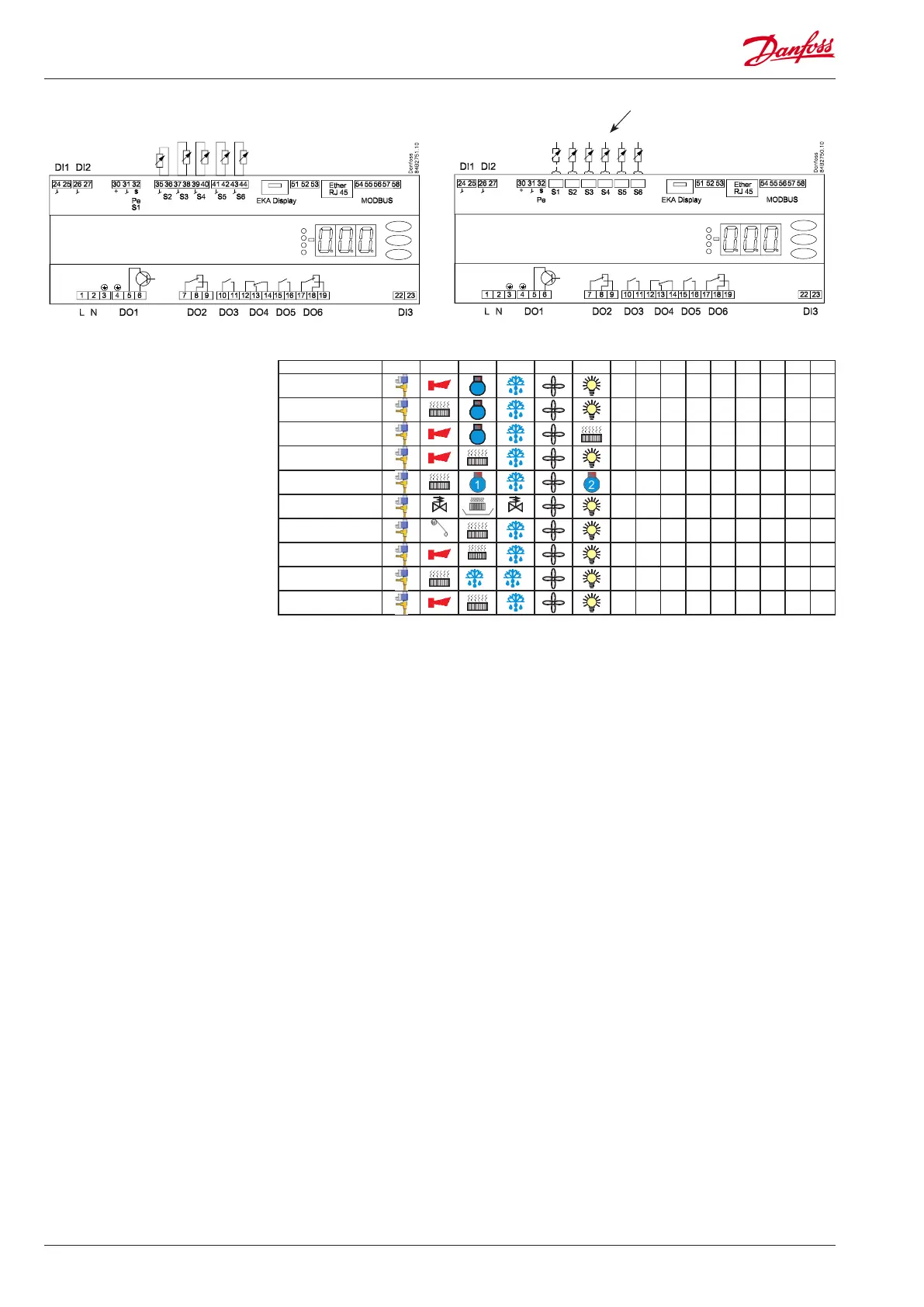
Connections
Version where sensor
connectionshaveplug
connections.
Overview of outputs and
applications.
See also electrical diagrams earlier
in the manual
Application DO1 DO2 DO3 DO4 DO5 DO6 DI1 DI2 DI3 AI1 AI2 AI3 AI4 AI5 AI6
1
• • •
P0/S1 S2 S3 S4 S5 S6
2
• • •
P0/S1 S2 S3 S4 S5 S6
3
• • •
P0/S1 S2 S3 S4 S5 S6
4
• • •
P0/S1 S2 S3 S4 S5 S6
5
• • •
P0/S1 S2 S3 S4 S5 S6
6
suction
hotgas
• • •
P0/S1 S2 S3 S4 S5 S6
7
Blinds
• • •
P0/S1 S2 S3 S4 S5 S6
8
heat
• • •
P0/S1 S2 S3 S4 S5 S6
9
2 1
• • •
P0/S1 S2 S3 S4 S5 S5B
10
• • •
P0/S1 S2 S3 S4 S5 S3B