AK-CC550 Manual RS8EN502 © Danfoss 02-2010 33
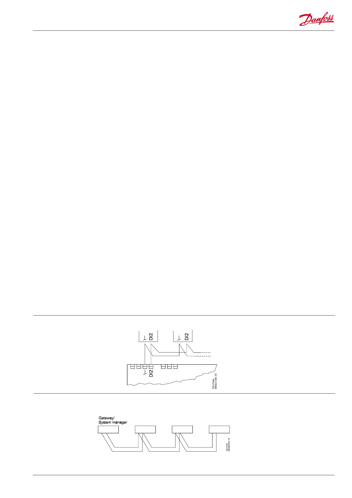
Coordinateddefrostvia
data communication
Coordinateddefrostvia
cable connections
The following controllers can be connected
up in this way:
EKC204A,AK-CC210,AK-CC250,
AK-CC450,AK-CC550,
Refrigeration is resumed when all
controllershave“released”thesignalfor
defrost.
The setting of controllers to coordinate
theirdefrostingtakesplaceinthe
gateway/systemmanager.
Refrigeration is resumed when all
controllershave“released”thesignalfor
defrost.
DO1
ConnectionofexpansionvalvetypeAKVorAKVA.Thecoilmust
be a 230 V a.c. coil.
DO2
Alarm
Thereisaconnectionbetweenterminal7and8inalarm
situations and when the controller is without power.
Rail heat and heating element in drip tray
Thereisconnectionbetweenterminal7and9whenheating
takesplace.
Night blind
Thereisconnectionbetweenterminal7and9whenthenight
blind is up.
Suction line valve
Thereisconnectionbetweenterminal7and9whenthe
suction line must be open.
DO3
Refrigeration, Rail heat, Heat function, Defrost 2
There is connection between terminal 10 and 11 when the
functionmustbeactive.
Heating element in drip tray
There is connection between terminal 10 and 11 when heating
takesplace.
DO4
Defrost
Thereisconnectionbetweenterminal12and14when
defrostingtakesplace.
Hotgas/drainvalve
Thereisconnectionbetweenterminal13and14duringnormal
operation.
Thereisconnectionbetweenterminal12and14whenthehot
gasvalvesmustopen.
DO5
Fan
Thereisconnectionbetweenterminal15and16whenthefan
is on.
DO6
Light relay
Thereisconnectionbetweenterminal17and18whenthe
light must be on.
Rail heat, Compressor 2
Thereisconnectionbetweenterminal17and19whenthe
functionmustbeactive.
DI3
Digital input signal.
Thesignalmusthaveavoltageof0/230VAC.
Thefunctionisdenedino84.
Data communication
Ifdatacommunicationisused,itisimportantthattheinstallation
of the data communication cable is performed correctly.
See separate literature No. RC8AC…
Electric noise
Cablesforsensors,DIinputsanddatacommunicationmust be
keptseparatefromotherelectriccables:
-Useseparatecabletrays
- Keep a distance between cables of at least 10 cm
-LongcablesattheDIinputshouldbeavoided
Installation considerations
Accidentaldamage,poorinstallation,orsiteconditions,cangive
rise to malfunctions of the control system, and ultimately lead to a
plantbreakdown.
Everypossiblesafeguardisincorporatedintoourproductsto
preventthis.However,awronginstallation,forexample,couldstill
present problems. Electronic controls are no substitute for normal,
good engineering practice.
Danfoss will not be responsible for any goods, or plant compo-
nents,damagedasaresultoftheabovedefects.Itistheinstaller's
responsibilitytochecktheinstallationthoroughly,andtotthe
necessarysafetydevices.
Special reference is made to the necessity of signals to the
controller when the compressor is stopped and to the need of
liquidreceiversbeforethecompressors.
YourlocalDanfossagentwillbepleasedtoassistwithfurther
advice,etc.
Max. 10