10 Instructions RI8LN802 © Danfoss 2/2012 AK-CC 550
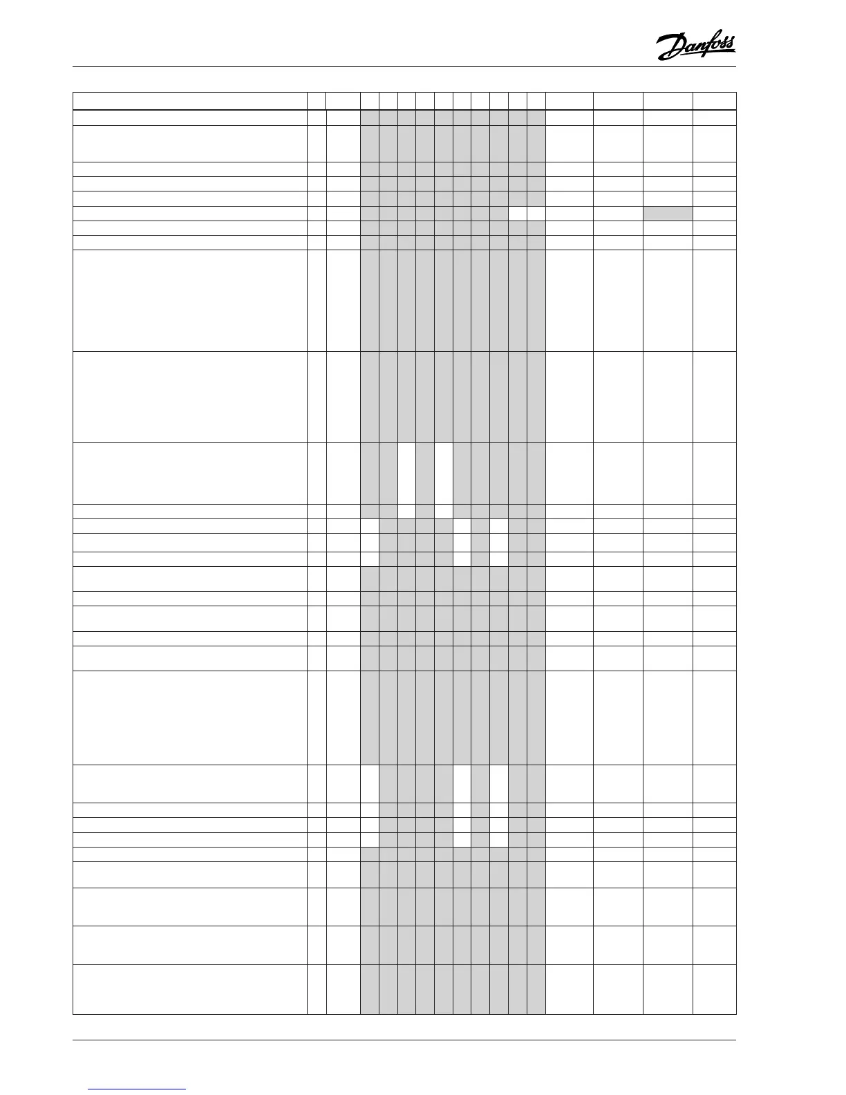
Continued Code 1 2 3 4 5 6 7 8 9 10 Min. Max. Fac. Actual
Network address (0 = off)
o03 1 1 1 1 1 1 1 1 1 1 0 240 0
On/Off switch (Service Pin message)
IMPORTANT! o61 must be set prior to o04
(used at LON 485 only)
o04 1 1 1 1 1 1 1 1 1 1 0/Off 1/On 0/Off
Access code 1 (all settings)
o05 1 1 1 1 1 1 1 1 1 1 0 100 0
Used sensor type : 0=Pt1000, 1=Ptc1000, o06 1 1 1 1 1 1 1 1 1 1 0/Pt 1/Ptc 0/Pt
Max hold time after coordinated defrost
o16 1 1 1 1 1 1 1 1 1 1 0 min. 360 min. 20
Select signal for display view. S4% (100%=S4, 0%=S3)
o17 1 1 1 1 1 1 1 1 0 % 100 % 100
Pressure transmitter working range – min. value
o20 1 1 1 1 1 1 1 1 1 1 -1 bar 5 bar -1
Pressure transmitter working range – max. value
o21 1 1 1 1 1 1 1 1 1 1 6 bar 200 bar 12
Refrigerant setting:
1=R12. 2=R22. 3=R134a. 4=R502. 5=R717. 6=R13.
7=R13b1. 8=R23. 9=R500. 10=R503. 11=R114.
12=R142b. 13=User defined. 14=R32. 15=R227.
16=R401A. 17=R507. 18=R402A. 19=R404A. 20=R407C.
21=R407A. 22=R407B. 23=R410A. 24=R170. 25=R290.
26=R600. 27=R600a. 28=R744. 29=R1270. 30=R417A.
31=R422A.
o30 1 1 1 1 1 1 1 1 1 1 0 31 0
Input signal on DI2. Function:
(0=not used. 1=status on DI2. 2=door function with alarm
when open. 3=door alarm when open. 4=defrost start
(pulse-signal). 5=ext. main switch 6=night operation
7=thermostat band changeover (activate r21). 8=alarm
function when closed. 9=alarm function when open.
10=case cleaning (pulse signal). 11=forced cooling at hot
gas defrost.). 12=night cover, 13=coordinated defrost)
o37 1 1 1 1 1 1 1 1 1 1 0 13 0
Configuration of light function: 1=Light follows day /night
operation, 2=Light control via data communication
via ‘o39’, 3=Light control with a DI-input, 4=As "2", but
light switch on and night cover will open if the network
cut out for more than 15 minutes.
o38 1 1 1 1 1 1 1 1 1 4 1
Activation of light relay (only if o38=2) On=light o39 1 1 1 1 1 1 1 1 0/Off 1/On 0/Off
Rail heat On time during day operations
o41 1 1 1 1 1 1 1 0 % 100 % 100
Rail heat On time during night operations
o42 1 1 1 1 1 1 1 0 % 100 % 100
Rail heat period time (On time + Off time)
o43 1 1 1 1 1 1 1 6 min. 60 min. 10
Case cleaning. 0=no case cleaning. 1=Fans only. 2=All
output Off.
*** o46 1 1 1 1 1 1 1 1 1 1 0 2 0
Selection of EL diagram. See overview page 2 and 3
* o61 1 1 1 1 1 1 1 1 1 1 1 10 1
Download a set of predetermined settings. See overview
page 15.
* o62 1 1 1 1 1 1 1 1 1 1 0 6 0
Access code 2 (partial access)
*** o64 1 1 1 1 1 1 1 1 1 1 0 100 0
Replace the controllers factory settings with the present
settings
o67 1 1 1 1 1 1 1 1 1 1 0/Off 1/On 0/Off
Input signal on DI3. Function: (high voltage input)
(0=not used. 1=status on DI2. 2=door function with alarm
when open. 3=door alarm when open. 4=defrost start
(pulse-signal). 5=ext. main switch 6=night operation,
7=thermostat band changeover (activate r21). 8=Not used.
9=Not used. 10=case cleaning (pulse signal). 11=forced
cooling at hot gas defrost, 12=night cover. 13=Not used.
14=Refrigeration stopped (forced closing))
o84 1 1 1 1 1 1 1 1 1 1 0 14 0
Rail heat control
0=not used, 1=pulse control with timer function (o41
and o42), 2=pulse control with dew point function
o85 1 1 1 1 1 1 1 0 2 0
Dew point value where the rail heat is minimum o86 1 1 1 1 1 1 1 -10°C 50°C 8
Dew point value where the rail heat is 100% on o87 1 1 1 1 1 1 1 -9°C 50°C 17
Lowest permitted rail heat effect in % o88 1 1 1 1 1 1 1 0 % 100 % 30
Time delay from "open door” refrigeration is started o89 1 1 1 1 1 1 1 1 1 1 0 min. 240 min. 30
Fan operation on stopped refrigeration (forced closing):
no/0=Fan Off, yes/1=Fan On
o90 1 1 1 1 1 1 1 1 1 1 0/no 1/yes 1/yes
Definition of readings on lower button:
1=defrost stop temperature, 2=S6 temperature,
3=S5_B temperature
o92 1 1 1 1 1 1 1 1 1 1 1 3 1
Display of temperature
1= u56 Air temperature
2= u36 product temperature
o97 1 1 1 1 1 1 1 1 1 1 1 2 1
Light and night blinds defined
0: Light is switch off and night blind is open when the
main switch is off
1: Light and night blind is independent of main switch
o98 1 1 1 1 1 1 1 1 1 1 0 1 0

 Loading...


