12 Manual RS8EJ302 © Danfoss 05-2010 AK-PC 530
Output signal from AK-PC 530
In EKC 331 the voltage range must be set to 0-5 V (“o10” = 6).
In EKC 331 the number of steps must be set to 4 (“o19” = 4) (also when
fewer fans are connected).
Output signal from AK-PC 530
In the rst EKC 331, set 0-5 V (“o10” = 6).
In the second EKC 331, set 5-10 V (“o10” = 7).
In both EKC’s the number of steps must be set to 4 (“o19” = 4) (also when
fewer fans are connected to the second EKC).
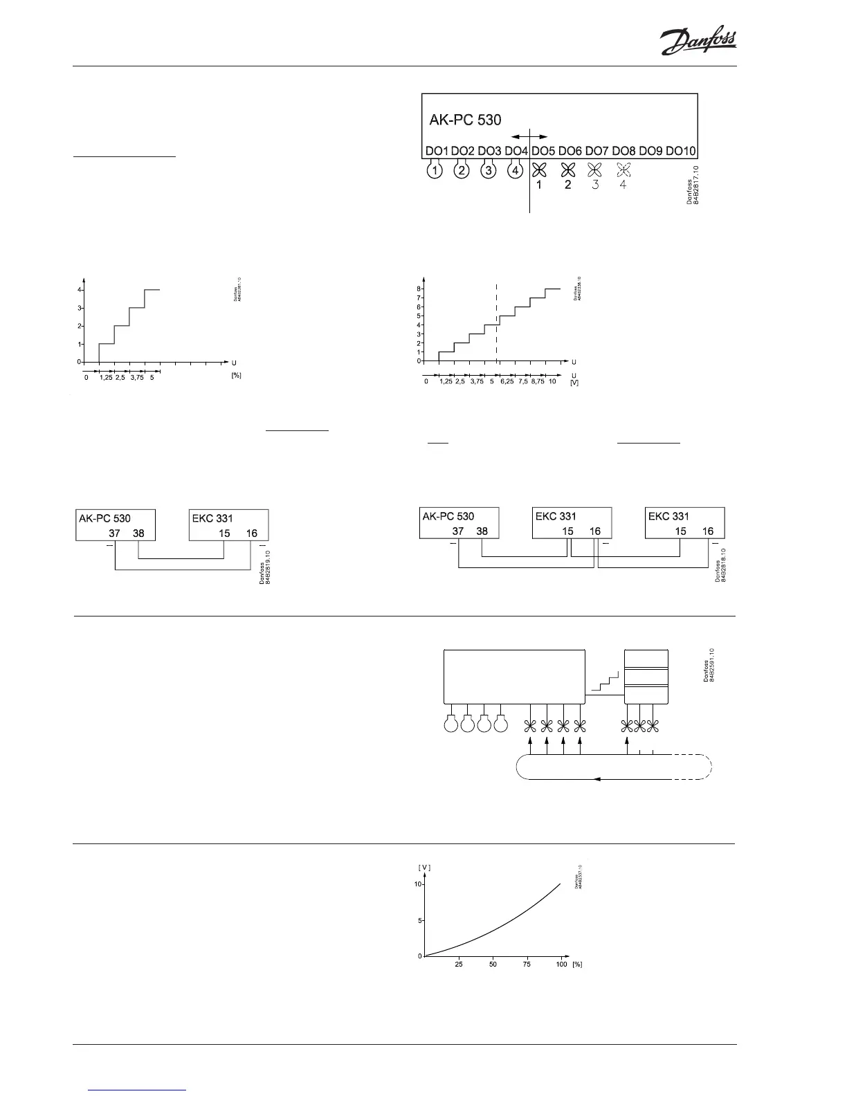
If the entire condenser capacity is to be controlled by
a frequency converter, AK-PC 530 must send an analog
signal about the required capacity (“c29” = 9).
The signal varies from 0 to 10 V. Signal and capacity
have the following context.
Condenser couplings
When the compressor relays have been established the turn
comes to the fan relays.
The rst vacant relay (DO1-DO8) will become the rst fan relay.
It will be followed by the subsequent relays. If more relays are
required than the vacant DO relays, a relay module can be
connected to the analog output. The function is, as follows:
If there are up to four external fans on an EKC 331:
1. 2.
If there are more than four external fans on two EKC 331 units:
Connection
Connection
Alternating start-up of fans (only if c29 is 11 to 18)
The fans can be dened to start alternately when they have all
been stopped.
The rst time regulation is started, fan 1 will be started rst – the
regulation determines whether additional fans will be started.
After the next time all fans are stopped, fan 2 will be the rst to be
started, and so on.
Fan 1 will again be the rst fan to be started when the rotation has
been through the total number of fans.
If there is more than one fan on an EKC 331, it will not be possible
to start the other fans rst. Here, the fan with the lowest voltage
step will always be the one which is started rst.