4 DKRCI.PD.SC0.C3.02 / 520H5687 © Danfoss A/S (AC-MCI/MWA), 2012-05
Liquid Level Sensor, AKS 4100/4100U
Coaxial version
The Coaxial version consists of:
Signal Converter (with or without HMI)
Mechanical process connection with
5 m (197 in.) Ø2 mm (0.08 in.) stainless
wire
Tube(s) depending on required length
Accessory bag comprising:
End Connector (incl. 3 mm (0.12 in.)
set screws.)
3 mm (0.12 in.) set crews (1 set screw pr. tube)
Red cover to protect mechanical process
connection , before Signal Converter
is mounted.
Setting label.
The coaxial version is available
in the following probe lengths:
AKS 4100, 500 mm
AKS 4100, 800 mm
AKS 4100, 1000 mm
AKS 4100, 1200 mm
AKS 4100, 1500 mm
AKS 4100, 1700 mm
AKS 4100, 2200 mm
AKS 4100U, 19.2 in.
AKS 4100U, 30 in.
AKS 4100U, 45 in.
AKS 4100U, 55 in.
AKS 4100U, 65 in.
AKS 4100U, 85 in.
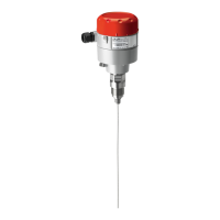
Coaxial version
AKS 4100/4100U, Coaxial can be installed
in a standpipe (a) or directly in a vessel (b).
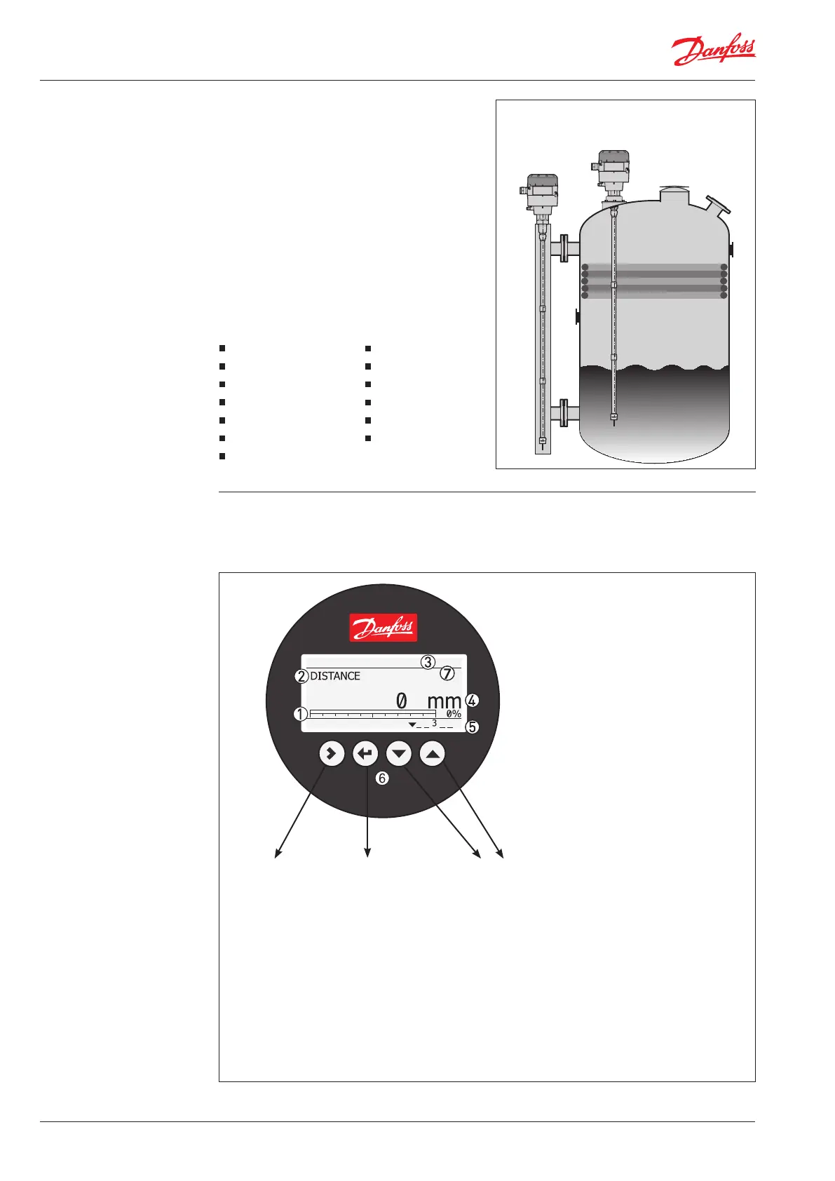
Optional HMI
4-20 mA output displayed as bar graph
and in percentage [%]
Measurement name (in this example,
DISTANCE)
Device tag name
➃
Measurement reading and unit
➄
Device status (markers)
1 = Hardware problem (any hardware
problem making the device unable to
provide a correct measurement
(communication, memory problem…)
2 = No Reference Pulse
3 = Low Voltage or Measurement Old
4 = Level Lost
➅
Keypad buttons
➆
Flashing star indicating unit in operation.
Enter menu system
Enter QUICK SETUP
Unit change at
distance/level
readout:
m, cm, mm, in, ft
Change between:
Distance*
Level**
Output (%)***
Output (mA)****
*
AKS 4100
The optional HMI Service/Display unit is used for
commissioning and quick on-site setup and is
easily mounted on the AKS 4100/4100U.
The service unit supports mulitple languages in
both SI and US units.
Supported standard languages:
English (default), German, French, Spanish
a
b
* DISTANCE is a display option.
If the display is set to “DISTANCE” the displayed
value will be the distance from the Reference
point to the top surface of the liquid refrige-
rant (see page 7 and 8).
** LEVEL is display option.
If the display is set to “LEVEL” then the value
displayed will be:
PROBE LENGTH (entered in QUICK SETUP)
– DISTANCE (see page 7 and 8).
*** OUTPUT (%) is display option.
Will represent the level of refrigerant,in
percent, scaled (entered in QUICK SETUP)
according to: SCALE 4 mA (0%), SCALE 20
mA (100%) (see page 7 and 8)
**** OUTPUT I (mA) is display option.
Will represent the level of refrigerant,in 4-20
milliampere, scaled (entered in QUICK
SETUP) according to: SCALE 4 mA (4 mA),
SCALE 20 mA (20 mA) (see page 7 and 8).

 Loading...