AQ47215075356901-010101 7 | © Danfoss | 2024.11
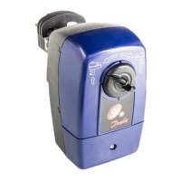
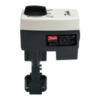
AME 435
ENGLISH
Safety Note
To avoid injury of persons and
damages to the device, it is absolutely
necessary to read and observe these
instructions carefully.
Necessary assembly, start-up, and maintenance
work must be performed by qualified and
authorized personnel only.
Prior to assembly and depressurizing the
system.
Please comply with the instructions of the
system manufacturer or system operator.
Do not remove the cover before the
power supply is fully switched off.
Mounting and installation ❶
Wiring ❷
Do not touch anything on the PCB!
Switch off the power line before
wiring the actuator!
Lethal voltage!
Wire the actuator according to the wiring
diagram.
Functions accessible from cover
With MODE-button located on the top of the
cover it is possible to enter two function modes.
Self stroking mode ❸
Self stroking mode starts automatically the
first time when power supply is applied to
the actuator. To manually start self stroking
procedure afterwards press and hold button for
6-9 seconds until the green light starts flashing.
Self stroking procedure starts with extracting
the actuator stem. When maximum force
is detected (at the end valve position) the
actuator retracts the stem until the maximum
force is detected again (on the other valve end
position).
End positions are set and the actuator goes
to normal mode and starts responding to the
control signal.
STAND-BY MODE
- Manual operation ❹
Press the STAND-BY/RESET-button for 3-6 sec.
to enter STAND-BY mode. The actuator stops
in current position and stops responding to
any control signal. Red light is flashing in 2 sec.
interval. You can manually control the actuator
(manual operation- see next section).
This mode can be very useful during the
commissioning of other equipment, or for
service purposes.
To exit Stand by mode press the
STAND-BY/RESET-button again.
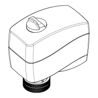
Manual operation
Manual operation can be done by means of
control knob on actuator housing.
To manually operate the actuator:
• Disconnect control signal
• Adjust valve position using the control knob
(observe the rotation direction)
To go back to automatic operation restore the
control signal.
NOTE:
When the manual operation has been used, the
output signal (X) is not accurate until the actuator
reaches its end position.
DIP switch settings ❺
DIP switches
U I
0-10 V 2-10 V
DIR INV
FAST SLOW
--- 3s/m
LIN LOG
ACT SMART
Factory settings:
ALL switches are in OFF position!
NOTE:
All combinations of DIP switches are allowed.
All functions that are selected are added
consecutively.
SW 1: U/I Input signal type selector
SW 2: Input signal range selector ②
SW 3: Direct or Inverse acting selector③
- OFF position; the actuator is in direct acting
mode (stem extracts as voltage increases)
- ON position; the actuator is in inverse acting
mode (stem retracts as voltage increases)
SW 4: Fast/Slow
- Speed selector ④
SW 5: Normal or very high speed
SW 6: Not used
SW 7: Linear or equal-percentage flow
through valve selector ❻
- OFF position; the valve position is linear acc.
to the control signal
- ON position; the valve position is equal-
percentage acc. to the control signal. This
relation is adjustable - see
Equal-percentage valve-flow adjustment
section
SW 8: Smart function selector ❼
- OFF position; the actuator does not try to
detect oscillations in the system
- ON position; actuator enables special anti
oscillations algorithm – see Anti oscillations
algorithm section
LED operating mode indicator ❽
Green LED:
• Flashing once per sec. ①
- Self stroking mode
• Lit ②
- Operating mode – actuator is moving to Y
signal position
• Flashing once every 6 sec. ③
- Stationary mode – actuator reached Y
signal set point
Red LED:
• Flashing twice per second ④
- STAND-BY MODE – actuator stopped
and not responding to Y signal - manual
operation enabled
• Lit ⑤
- Error mode – power supply to low, initial
self positioning time too short due to
too short valve strokes, failure during self
calibration
• Dark / no lights:
- No power supply
Dismounting ❾
Dimensions ❿
The following information is provided on the
device or on the instruction manual or
datasheet:
A) Purpose of control: Electrical Actuator
B) Construction of control: Independently
Mounted Control
C) Method of mounting control
D) Type 1 Action
E) Pollution Degree 2
F) Impulse Voltage: 500V
G) Software Class A
H) Mechanical and thermal ratings (ref to
Ratings section for more details)
I) “Use ½ inch flexible metal conduit for
connection”
J) “Use Listed Flexible Metal Conduit Fitting
DWTT/7”
K) “Use 60°C/75°C copper (CU) conductor and wire
size range (#) AWG, stranded or solid”.
“The terminal tightening torque of (#) Lb per In.”
L) Torque value for Cover screw: 0,6 +/-0,1 Nm.
Note (#): Values depend by field wiring ratings of terminal
block employed on the device construction.
Part Name
Hazardous Substances Table
Lead (Pb) Mercury (Hg) Cadmium (Cd) Hexavalent Chromium (Cr(VI)) Polybrominated biphenyls (PBB) Polybrominated diphenyl ethers (PBDE)
O: Indicates that this hazardous substance contained in all of the homogeneous material for this part is below the limit requirement in GB/T 26572;
 Loading...