Do you have a question about the Danfoss AME 110 NLX and is the answer not in the manual?
Crucial instructions for preventing injury and device damage during operation and maintenance.
Guidelines for dismantling and disposing of the product and its components according to local regulations.
Instructions on how to mount the actuator onto the valve body using a ribbed nut.
Guidelines for wiring the actuator, emphasizing safety precautions like switching off power.
Explanation of the auto sleep mode function and how to re-activate learning mode.
Procedure for checking the valve neck and securely mounting the actuator.
Details on factory settings and how to configure the actuator using DIP switches.
Configures the input signal range for voltage or current inputs.
Selects whether the actuator stem contracts or extends with increasing voltage.
Determines if the actuator operates in a standard or sequential signal range.
Sets the specific ranges for sequential mode operation (0-5V/5-10V).
Configures the valve flow characteristic as linear or equal percentage.
Enables an anti-blocking exercise for the valve to prevent seizing.
Selects between voltage (U) or current (I) as the input signal type.
Initiates a self-stroking cycle for the actuator.
Procedure for manually operating the actuator drive for service purposes.
Interpreting the status indicated by the red and green light emitting diodes.
Provides physical dimensions (L, H, b) for AME 110 NLX + AB-QM valve sizes DN 10-32.
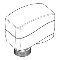
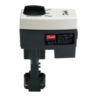
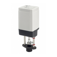
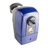
This document describes the Danfoss AME 110 NLX, an actuator designed for modulating control in various heating and cooling applications. It is intended for use with AB-QM DN 10-32 valves.
The AME 110 NLX actuator provides modulating control, allowing for precise regulation of flow through a valve. It receives an input signal (either voltage or current) and adjusts the valve stem position accordingly. The actuator can operate in direct or inverse acting modes, meaning the stem can either contract or extract as the input signal increases.
The device offers flexible input signal ranges, selectable via DIP switches. Users can choose between 2-10 V or 4-20 mA, or 0-10 V or 0-20 mA. This adaptability ensures compatibility with a wide range of control systems. For specialized applications, sequential mode operation is available, allowing the actuator to respond to specific segments of the input signal range, such as 0(2)-5(6) V, 0(4)-10(12) mA, 5(6)-10 V, or 10(12)-20 mA.
The actuator also supports different flow characteristics. It can be configured for linear flow, where the valve position is directly proportional to the control signal, or for equal percentage flow, which provides a logarithmic relationship between valve position and flow, often preferred for better control authority at lower flow rates.
An "Anti-blocking function" (ASTK) is integrated to prevent valve seizure during periods of inactivity. When enabled, the actuator periodically exercises the valve by opening and closing it every seven days, ensuring smooth operation and extending the valve's lifespan.
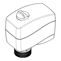
A reset button is provided, which initiates a self-stroking cycle, allowing the actuator to recalibrate its position. Manual override is also available for service purposes, enabling technicians to adjust the valve position without power, though it's crucial to disconnect power before engaging this feature.
The actuator features LED indicators that provide visual feedback on its operational status, including direction of movement, normal operation, self-adjusting mode, and various fault conditions such as low power supply or calibration failures.
The AME 110 NLX is designed for straightforward installation and operation. It can be mounted with the valve stem in either a horizontal position or pointing upwards. The actuator is secured to the valve body using a ribbed nut, which can be tightened by hand, eliminating the need for specialized tools.
Wiring is simplified with clearly labeled terminals for 24 V AC power, input signals (Red, Grey, Black, White for 24 V, Y, Common, X respectively), and safety isolation. It is critical to connect via a safety isolating transformer and to switch off the power supply before any wiring work to prevent injury.
The DIP switches allow for easy configuration of various operational parameters, including input signal range, acting mode (direct/inverse), sequential mode, and flow characteristic (linear/equal percentage). Factory settings ensure a default configuration, with most switches in the OFF position, except for SW 1.
An "Auto sleep mode" is implemented for situations where the actuator is powered but not yet installed on a valve. After five minutes of inactivity, the actuator will move to its lowest position and turn off all LED indicators. To reactivate it for learning mode, the RESET button must be pressed or the power supply cycled. It is important to drive the spindle to the upper position before installing the actuator on an AB-QM valve.
The AME 110 NLX is designed to be "MAINTENANCE FREE," indicating that it requires minimal ongoing service. Its robust construction and the anti-blocking function contribute to its long-term reliability.
The LED indicators serve as a primary diagnostic tool, allowing users and technicians to quickly assess the actuator's status and identify potential issues without complex equipment. Different flashing patterns and colors indicate specific operational states or error conditions, facilitating troubleshooting.
The ability to manually override the actuator's position is a key maintenance feature, allowing for mechanical adjustments or valve testing during service, provided power is disconnected.
The product is designed for responsible disposal, with components sorted into various groups for recycling, aligning with local regulations. This consideration for end-of-life management reflects a commitment to environmental responsibility.
Overall, the AME 110 NLX combines advanced control capabilities with user-friendly installation and minimal maintenance requirements, making it a reliable choice for modulating control applications.
| Type | Actuator |
|---|---|
| Power supply | 24 V AC/DC |
| Torque | 10 Nm |
| Protection class | IP54 |
| Housing material | Plastic |
| Input signal | 0-10 V, 4-20 mA |
| Ambient temperature | -10 ... 55 °C |