


T
tylerlewisJul 25, 2025
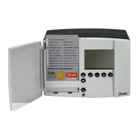
What to do if my Danfoss Gateway indicates a communication error on the ECL?
- PPaige WilliamsJul 25, 2025
If your Danfoss Link™ indicates a communication error on the ECL and the DLG for ECL has a green light, it might be caused by an unstable or disconnected cable connection between the ECL and the DLG. Check the cable connection for defects. Fasten the screw terminals, and if the error persists, the cable has to be changed.