EasyManua.ls Logo

Danfoss AME213 - User Manual

Danfoss AME213
46 pages
Go to English
Print Icon
To Next Page IconTo Next Page
Loading...
Bedienungsanleitung / Operating Instructions
600 000 7072
Ausgabe 2 / 6.02
VI.AB.I2.5B
Danfoss IWK
Regler GmbH
Elektrischer Stellantrieb Seite 2
Electrical Actuator Page 24
AMV213 / AME213
mit Sicherheitsfunktion
with Safety Function
AMV210 / AME210
AMV(E)210, 213 /
VIM2, VIU2
AMV(E)210, 213 /
VIS2
AMV(E)210, 213 /
AIQM, V63M

Table of Contents

Questions and Answers

  • C
    Cassandra SchultzAug 7, 2025
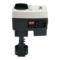
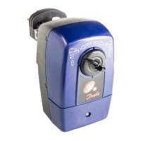
    What to do if Danfoss AME213 Controller actuators are not working?
    • A
      Andrew KaiserAug 7, 2025
      If your Danfoss Controller actuators aren't functioning, start by verifying the power connection. Then, check the electrical control unit for a control signal. Also, make sure the safety unit (STB, STW, or SDB) hasn't been triggered. If it has, check the system and safety unit. For AME2 models, ensure the DIP switch is set to automatic operation.
  • D
    Deanna ParkerAug 22, 2025
    Why is the Danfoss AME213 actuator direction reversed?
    • J
      jasongilmoreAug 22, 2025
      If the effective direction of your Danfoss Controller actuator is reversed, for AMV2 models, check and change the terminal connections at terminals 6 and 7. For AME2 models, verify that the DIP switch is set to normal operation.

Summary

Safety Notes

Mounting

Mounting the Actuator on the Valve

Provides step-by-step instructions for physically attaching the actuator to the valve.

Electrical Connection

Details the process and safety precautions for connecting electrical wiring to the actuator.

Connection Diagram

Presents wiring diagrams for connecting AMV210 and AMV213 actuators and end switches.

Mechanical Stroke Setting

Valve Types VIG2, VIS2, VIU2, AIQM

Explains how to set the mechanical stroke for specific valve types, including initial steps and closure.

Adjustments AME210, AME213

Setting the End Positions

Details the procedure for aligning the actuator's end positions (valve open/closed) using voltage and current signals.

Manual Adjustment

Troubleshooting

Fault, cause, remedy

Provides a table listing common actuator faults, their possible causes, and recommended remedies.

Fault Indicator Actuators AME210, 213

Explains how to interpret fault indications from LEDs and output signals on AME210/AME213 actuators.

Danfoss AME213 Specifications

General IconGeneral
Input voltage24 V AC/DC
Protection classIP54
Housing materialPlastic
Temperature range-20°C to +60°C
Operating temperature-20°C to +60°C

Related product manuals