EasyManua.ls Logo

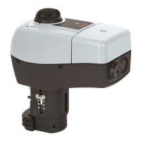
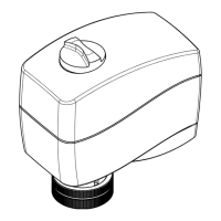
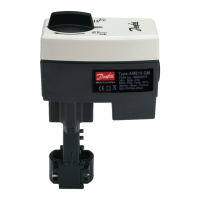
Danfoss AMV213

Danfoss AMV213
46 pages
Go to English
To Next Page IconTo Next Page
Loading...
Bedienungsanleitung / Operating Instructions
600 000 7072
Ausgabe 2 / 6.02
VI.AB.I2.5B
Danfoss IWK
Regler GmbH
Elektrischer Stellantrieb Seite 2
Electrical Actuator Page 24
AMV213 / AME213
mit Sicherheitsfunktion
with Safety Function
AMV210 / AME210
AMV(E)210, 213 /
VIM2, VIU2
AMV(E)210, 213 /
VIS2
AMV(E)210, 213 /
AIQM, V63M

Table of Contents

Questions and Answers:

Danfoss AMV213 Specifications

General IconGeneral
BrandDanfoss
ModelAMV213
CategoryController
LanguageEnglish

Summary

1 Safety Notes

2 General Information

2.1 Definition of Application

Specifies the electrical actuator's use for Danfoss valves DN 15-50 and PN 16/25.

2.2 Transportation, Delivery, and Storage

Details permissible ambient conditions and verification of delivery.

2.3 Warranty

Explains warranty claim requirements for proper assembly and commissioning.

3 Device Description

3.1 Construction

Illustrates the physical components and internal structure of the actuator.

3.2 Description

Explains the actuator's operation, motor, gear mechanism, and positioner.

3.3 Technical Data

Presents specifications for actuators including stroke, voltage, signals, and temperatures.

Additional Equipment (cannot be added later)

Details optional components like end switches that cannot be installed after initial purchase.

4 Valve Types for AMV(E)210, 213

5 Mounting

5.1 Permitted Installation Positions

Illustrates valid and invalid mounting orientations for different valve types (VIM2, AIQM, VIS2).

5.2 Mounting the Actuator on the Valve

Provides steps and safety precautions for mounting the actuator onto the valve.

5.3 Electrical Connection

Details the procedure and safety warnings for connecting electrical lines to the actuator.

5.4 Connection Diagram

Shows electrical connection diagrams for AMV210, AMV213, and end switches.

6 Mechanical Stroke Setting

6.1 Valve Types VIG2, VIS2, VIU2, AIQM

Details the procedure for setting the mechanical stroke on specific valve types.

6.2 Valve AIQM5

Details setting the stroke limiting screw for AIQM5 valves based on flow rate curves.

6.3 Flow Adjusting Curves AIQM5

Presents flow rate curves for AIQM5 valves to adjust stroke limiting screw turns.

7 Adjustments AME210, AME213

7.1 Overview DIP switch settings

Explains the function of DIP switches for actuator configuration and operation modes.

7.2 Input Signal Settings

Details how to configure the actuator's input signal type and range (mA or V).

7.3 Output Signal Settings

Describes how to set the actuator's output signal type and range (V).

7.4 Assignment of the effective direction to the inputoutput signal

Explains how to set the actuator's response direction (normal/inverse) based on input/output signals.

7.5 Setting the End Positions

Details the process of aligning the actuator's end positions using voltage/current signals and LEDs.

8 Manual Adjustment

8.1 Actuator AMV210, AME210

Explains how to manually adjust the actuator stem using the rotary switch.

8.2 Actuator AMV213, AME213

Details manual stem adjustment for AMV213/AME213 using a hexagon socket screw key.

8.3 Actuator AME210, AME213

Describes electrical manual stem adjustment for AME210/AME213 actuators after cover removal.

9 Troubleshooting

9.1 Fault, cause, remedy

Provides a table listing common faults, their possible causes, and recommended remedies.

9.2 Fault Indicator Actuators AME210, 213

Explains how fault conditions are indicated by LEDs and output signals for AME210/213.

Related product manuals