2.6 DHP-AL, DHP-AL Opti
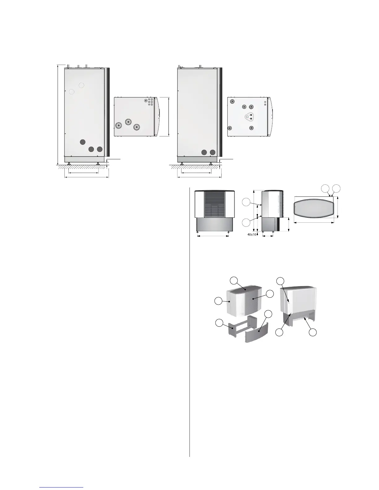
Dimensions and connections
The brine lines can be connected on either the left or right-hand
sides of the heat pump.
DHP-AL, DHP-AL Opti dimensions and connections.Figure 16:
Position Name
1 Brine in, 28 Cu
2 Brine out, during normal operation, 28 Cu
3 Brine out, during defrosting to hwh pos 8, 28 Cu
4 Return pipe from water heater pos 9, 28 Cu
5 Heating system supply line, 22 Cu: 6-10 kW, 28 Cu: 12 kW
6 Heating system return line, 22 Cu: 6-10 kW, 28 Cu: 12 kW
7 Lead-in power and sensor lead
Water heater
8 Connection for brine out when defrosting from pos 3
9 Water heater, return pipe to pos 4
10 Bleed valve, at stainless steel water heater
11 Brine out during defrosting, 28 Cu
12 Domestic hot water, 22 Cu
13 Cold water
14 Supply to water heater coil
15 Brine, expansion outlet when outdoor unit is positioned at high
level
16 Lead-in sensor lead
17 Safety valve for temperature and pressure (mounted only on cer-
tain models, see chapter 6)
Outdoor unit, dimensions and connections.Figure 17:
Position Name
1 Brine in, 28 Cu
2 Brine out, 28 Cu
Outdoor unit components and connections.Figure 18:
Position Name
1 Outdoor unit
2 Cover
3 Front cover
4 Stand
5 Cover
6 Connection, brine in
7 Connection, brine out
8 Connection, drain drip tray
Check that the delivery of the outdoor unit contains the following:
• Outdoorunit
• Disassembledstand
• Necessaryscrews,nutsandwashers.
• Defrostsensor
 Loading...