6.2 D system, DHP-L
With a DHP-L in a D system, the heat pump can produce both heat-
ing and hot water with the compressor and an external auxiliary
heater (oil boiler, electric boiler, district heating or similar) that is
located after the exchange valve replaces the integrated auxiliary
heater to produce heat.
The cables for the integrated auxiliary heater must be disconnect-
ed, which means that the heat pump cannot carry out peak heat
charging (legionella function). Peak heat charging must take place
with an electric heating element that is integrated in the water
heater or with an electric heating element on the supply line to the
water heater.
The heat pump control computer also controls an additional shunt.
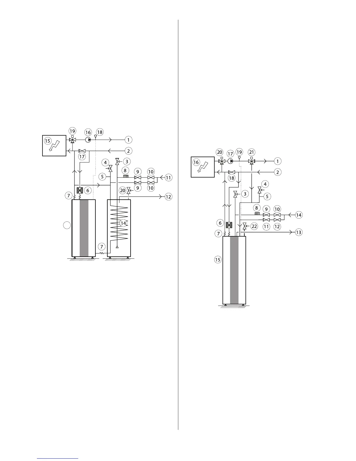
DHP-L, connection diagram D system
General connection diagram DHP-L, D system.Figure 47:
Position Name
1 Supply line
2 Return line
3 Safety valve cold water (9 bar) (included in delivery)
4 Safety valve expansion heating system
5 Expansion heating system
6 Strainer (part of the delivery)
7 Flexible hoses (part of the delivery)
8 Vacuum valve
9 Non-return valve
10 Shut-off valve
11 Cold water
12 Hot water
13 Heat pump (part of the delivery)
14 Water heater
15 External auxiliary heater
16 Circulation pump
17 Non-return valve
18 Moved supply line sensor (included in heat pump)
19 Auxiliary shunt
20 Safety valve for temperature and pressure (mounted only on cer-
tain models, see chapter 6)
6.3 VLD system, DHP-A, -AL
A VLD system is largely similar to a VL system, but with an external
auxiliary heater (often a boiler that is fired with solid fuel) in combi-
nation with a DHP-A or DHP-AL.
DHP-A’s integrated exchange valve is replaced by an exchange
valve that is located after the external auxiliary heater so that both
the heat pump and the auxiliary heater can produce heat and hot
water. The integrated exchange valve is disengaged with the flow
direction locked towards the heating system.
Production of heating and hot water cannot occur at the same time
because the exchange valve for heating/hot water is positioned
after the auxiliary heater. The integrated auxiliary heater carries
out peak heating charging (legionella function) in those operating
modes that permit auxiliary heat.
The heat pump’s control computer controls the external additional
heater via an output (283) on the defrosting card (factory installed
in DHP-A or DHP-AL). The heat pump control computer also con-
trols an additional shunt.
DHP-A, connection diagram VLD system
General connection diagram DHP-A, VLD system.Figure 48:
Position Name
1 Supply line
2 Return line
3 Safety valve cold water (9 bar) (included in delivery)
4 Safety valve expansion heating system
5 Expansion heating system
6 Strainer (part of the delivery)
7 Flexible hoses (part of the delivery)
8 Vacuum valve
9 Non-return valve
10 Shut-off valve
11 Non-return valve
12 Shut-off valve
13 Hot water
14 Cold water
15 Heat pump (part of the delivery)
16 External auxiliary heater
17 Circulation pump
18 Non-return valve
19 Moved supply line sensor (included in heat pump)
20 Auxiliary shunt
21 External exchange valve
22 Safety valve for temperature and pressure (mounted only on cer-
tain models, see chapter 6)
 Loading...