DHP-L, connection diagram VL system
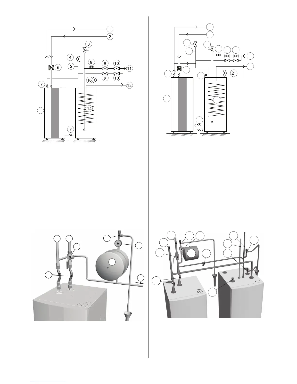
General connection diagram DHP-L.Figure 43:
Position Name
1 Supply line
2 Return line
3 Safety valve cold water (9 bar) (included in delivery)
4 Safety valve expansion heating system
5 Expansion heating system
6 Strainer (part of the delivery)
7 Flexible hoses (part of the delivery)
8 Vacuum valve
9 Non-return valve
10 Shut-off valve
11 Cold water
12 Hot water
13 Heat pump (part of the delivery)
14 Water heater
15 Manometer (not included
16 Safety valve for temperature and pressure (mounted only on cer-
tain models, see chapter 6)
Principal pipe connection DHP-L.Figure 44:
DHP-AL, connection diagram VL system
General connection diagram DHP-AL.Figure 45:
Position Name
1 Supply line
2 Return line
3 Heat pump (part of the delivery)
4 Safety valve
5 Expansion tank
6 Strainer (part of the delivery)
7 Flexible hoses (part of the delivery)
11 Safety valve (9 bar) (included in delivery)
12 Vacuum valve
13 Non-return valve
14 Shut-off valve
15 Cold water
16 Hot water
17 Water heater (part of the delivery)
18 Bleed valve at stainless steel water heater
19 Pressure gauge
20 Filler cock and non-return valve
21 Safety valve for temperature and pressure (mounted only on cer-
tain models, see chapter 6)
Principal pipe connection DHP-AL.Figure 46:
 Loading...