6 Piping installation
⚠
NOTE! To prevent leaks, ensure that there are no stresses in
the connecting pipes!
⚠
NOTE! It is important that the heating system is completely
bled after installation.
⚠
NOTE! The connection diagrams show general piping
arrangements. It is imperative that piping installation is
carried out in accordance with applicable local rules and
regulations. The hot water tank must be equipped with an
approved safety valve (supplied).
⚠
NOTE! Bleed valves must be installed where necessary.
⚠
NOTE! Danfoss SP (Single Phase) heat pumps are factory fit-
ted with a safety valve for temperature and pressure, 10 bar
90-95 °C, due to requirements in United Kingdom. The valve
is placed into the water tank and must not be used for other
purposes than discharge pipe connection.
Please also note that for DHP-H Opti Pro SP heat pumps it is
therefore imperative that the maximum hot water tempera-
ture is altered from the default factory setting from 95 °C to
85 °C. Refer to chapter 14.2 menu Service – HGW Parameter
MAX TEMP.
• Ensurethatthepipinginstallationfollowsthedimensionand
connection diagrams in section “Heat pump information”.
• ForUKspecificadviceonpipingarrangementspleaserefertothe
‘UK-specific appendix to Installation and Service Instructions'.
• Thepositionlistsshowthecomponentsandpartsincludedinthe
delivery in italics.
Selecting the heating system
The heat pump is set to VL system on delivery, that is with an inte-
grated electrical auxiliary heater and an exchange valve after the
auxiliary heater.
What determines which of the three systems VL, D or VLD should
be used is, among other things, how any auxiliary heater is used for
hot water production, and which model of heat pump is used.
6.1 VL system
In a VL system the heat pump can produce both heating and hot
water with the compressor and the integrated auxiliary heater.
Production of heating and hot water cannot occur at the same time
because the exchange valve for heating/hot water is positioned
after the auxiliary heater.
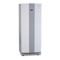
DHP-H, -C, -A, DHP-H Opti Pro, connection diagram VL
system
General connection diagram DHP-H, -C, -A, DHP-H Opti Pro.Figure 41:
Position Name
1 Supply line
2 Return line
3 Safety valve cold water (9 bar) (included in delivery)
4 Safety valve expansion heating system
5 Expansion heating system
6 Strainer (part of the delivery)
7 Flexible hoses (part of the delivery)
8 Vacuum valve
9 Non-return valve
10 Shut-off valve
11 Non-return valve
12 Shut-off valve
13 Hot water
14 Cold water
15 Heat pump (part of the delivery)
16 Pressure gauge
17 Expansion outlet Brine DHP-A
18 Safety valve for temperature and pressure (mounted only on cer-
tain models, see chapter 6)
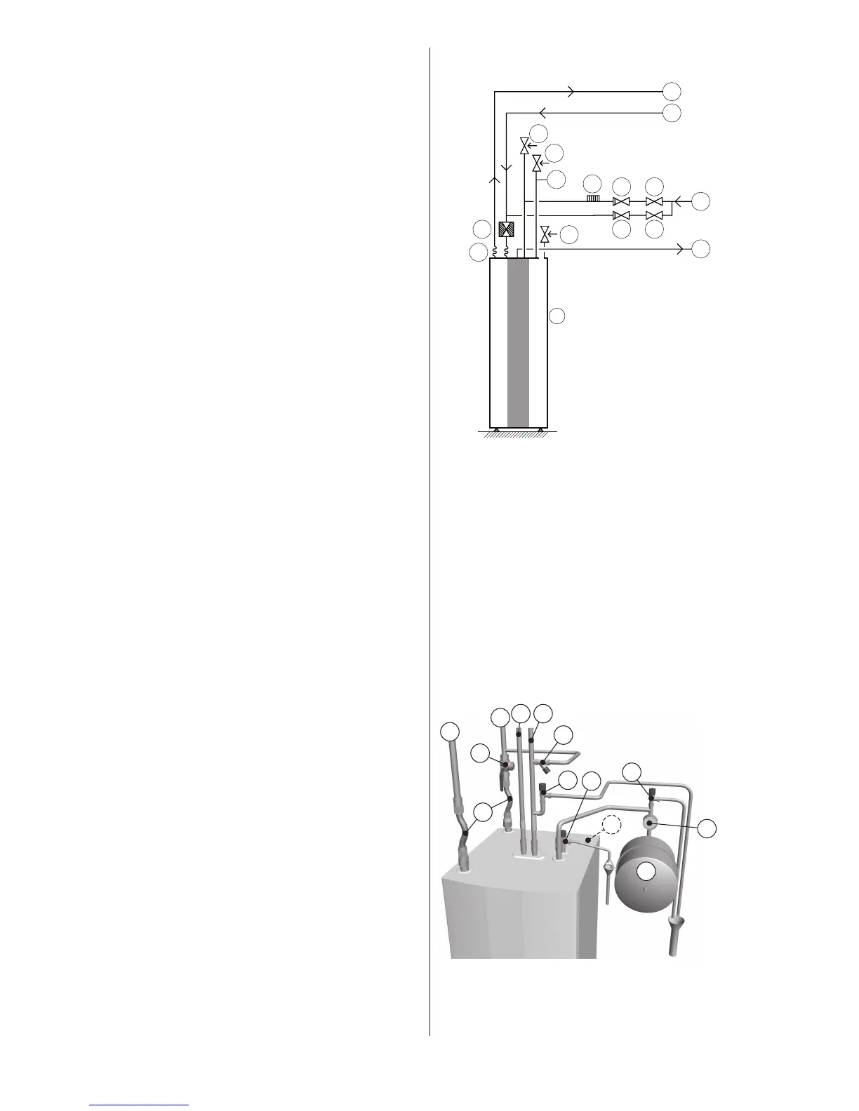
Principal pipe connection DHP-H, -C, -A, DHP-H Opti Pro.Figure 42:
 Loading...