2 Heat pump information
⚠
NOTE! The illustrations are schematic. Deviations from the
original are present.
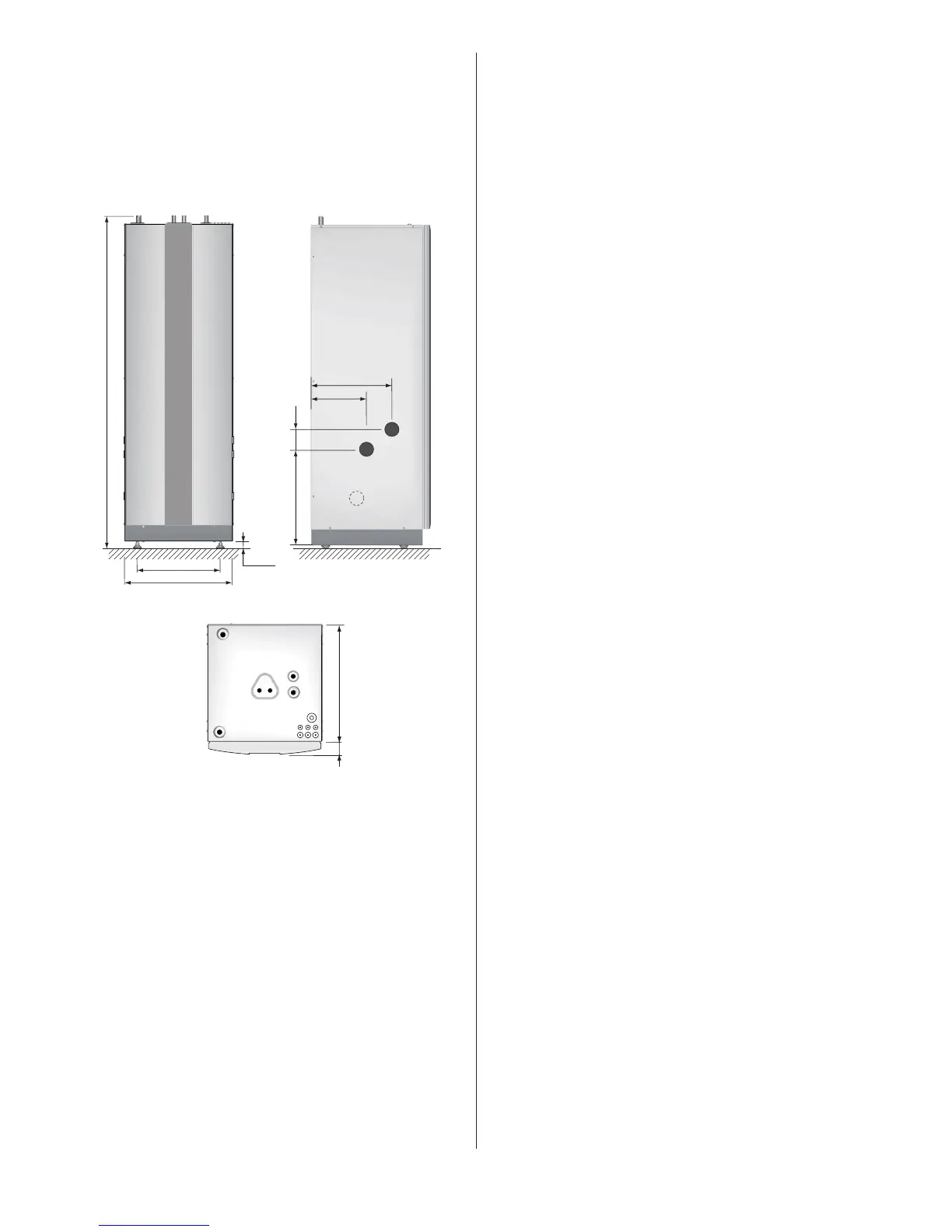
2.1 DHP-H
Dimensions and connections
DHP-H and connections.Figure 4:
The brine pipes can be connected on either the left or right-hand
sides of the heat pump.
Position Name
1 Brine in, 28 Cu
2 Brine out, 28 Cu
3 Heating system supply line, 22 Cu: 4-10 kW, 28 Cu: 12-16 kW
4 Heating system return line, 22 Cu: 4-10 kW, 28 Cu: 12-16 kW
5 Expansion line, 22 Cu
6 Hot water line, 22 Brass
7 Cold water line, 22 Brass
8 Lead-in for supply, sensor and communication cables
9 Safety valve for temperature and pressure (mounted only on cer-
tain models, see chapter 6)
 Loading...