Do you have a question about the Danfoss EKC 202B and is the answer not in the manual?
Details the controller's use in refrigeration and cold rooms, including defrost, fans, alarm, and light control.
Explains how the controller manages temperature and defrost cycles based on sensor input and relay outputs.
Lists benefits like integrated functions, IP65 density, digital input options, and programming key compatibility.
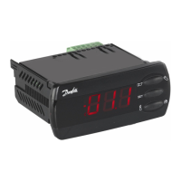
Controller with two relay outputs, two temp sensors, and digital input for temp control, defrost, and alarm.
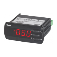
Controller with three relay outputs, two temp sensors, and digital input for temp, defrost, and fan control.
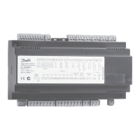
Controller with four relay outputs, two temp sensors, and digital input for temp, defrost, fan, and alarm/light control.
Lists functions for the digital input, including door contact, defrost start, regulation control, night operation, and case cleaning.
Explains a three-step process to steer the appliance through a cleaning phase, stopping and restarting refrigeration/fans.
Describes two methods for initiating defrost: based on aggregate refrigeration time or S5 temperature variation.
Explains the three-digit display and temperature unit settings (°C or °F), and the function of front panel LEDs.
Details the display indication (-d-) during defrost and conditions for its discontinuation.
Explains how to navigate menus and change settings using the buttons on the front panel.
Describes the normal display of temperature values from the Sair sensor and thermostat control settings.
Details settings for set point limitation, temperature unit, and display correction.
Explains Sair signal correction, start/stop of refrigeration, and night setback value settings.
Sets alarm delays for temperature and door alarms, and defines high/low temperature limits.
Sets the activation point for condenser temperature alarms using the S5 sensor.
Sets minimum ON and OFF times for the compressor to prevent irregular operation.
Selects defrost method (none, electric, gas) and sets the stop temperature.
Defines defrost interval, maximum duration, and time staggering for defrost cut-ins.
Configures fan operation (stopped or running) during defrost cycles and sets fan start delays.
Initiates defrost based on aggregate refrigeration time or S5 temperature variation.
Configures fan stop at compressor cutout, delay of fan stop, and fan stop temperature.
Manages the real-time clock for defrost scheduling and general timekeeping.
Lists functions for the digital input, including status display, door functions, defrost start, and main switch.
Sets controller address for networks and configures access codes for settings and adjustments.
Selects sensor type, display step, and configures the light relay function.
Transfers controller settings to a programming key or loads them from a key.
Defines the application of the S5 sensor and configures the function of relay 4.
Provides access to service-related data like sensor temperatures and relay statuses.
Lists fault messages, their types (A-alarms, E-alarms), and conditions for visibility.
Provides descriptions for various alarm codes, including temperature, door, and DI input alarms.
Defines the importance or destination settings for individual alarms.
Describes how defrost can be initiated via data communication or time schedule.
Explains how defrost control and time schedules are used for coordinated defrost and night setback.
Details how day/night control and time schedules manage the light function.
Specifies the required power supply voltage and details sensor connections.
Explains digital input functions and outlines general relay connections for various functions.
Provides guidelines for managing electric noise by separating sensor and communication cables.
| Supply voltage | 24 V AC/DC |
|---|---|
| Digital inputs | 2 |
| Analogue inputs | 1 |
| Number of relays | 2 |
| Relay Output | SPDT |
| Communication | Modbus RTU |
| Protection class | Class II |
| Storage temperature range | -20°C to 60°C |
| Relay contact rating | 250 V AC |
| Display | LED |
| Enclosure rating | IP65 (front) |
| Relative humidity | 20 to 80% RH, non-condensing |
| Mounting | DIN rail |
| Power consumption | Max 4 VA |