Do you have a question about the Danfoss EKC 531D1 and is the answer not in the manual?
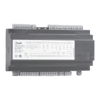
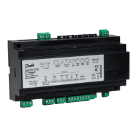
Details essential terminal connections for power, relays, and alarms.
Lists optional terminal connections for specific functions like external displays or alarms.
Explains wiring for unloader functionality and safety circuits.
Information on mounting and connecting data communication modules, including RJ45.
Defines compressor configurations using 'C16' and coupling modes using 'C08'.
Details capacity steps, sequential, cyclic, and binary operation modes.
Explains how to configure fan relays and connect external fans to EKC 331 units.
Describes sending an analog signal for condenser capacity control via a frequency converter.
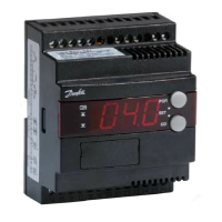
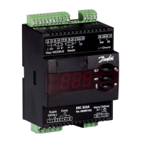
Explains how to display values and set temperature units (°C or °F).
Guides on navigating menus, changing values, and saving settings.
Provides a sequence of parameter adjustments for rapid system startup.
Details various parameters for PO reference, Pc reference, and capacity settings.
Covers parameters for sensors, operating hours, refrigerant type, and alarm settings.
Includes controller address, access code, sensor type selection, and supply voltage.
Lists possible error, alarm, and status messages displayed by the controller.
| Input Voltage | 24 V AC or DC |
|---|---|
| Communication | RS485 |
| Communication interface | RS485 |
| Relay Outputs | 2 |
| Output type | Relay |
| Weight | 0.3 kg |
| Type | Controller |
| Supply voltage | 24 V AC/DC |
| Storage temperature range | -40°C to +70°C |
| Relative humidity | 10 - 90 % RH |