4 Instructions RI8HU352 © Danfoss 12/2004 EKC 531D1
Operation
The buttons
When you want to change a setting, the two buttons will give you
a higher or lower value depending on the button you are push-
ing. But before you change the value, you must have access to the
menu. You obtain this by pushing the upper button for a couple
of seconds - you will then enter the column with parameter codes.
Find the parameter code you want to change and push the two
buttons simultaneously. When you have changed the value, save
the new value by once more pushing the two buttons simultane-
ously.
Gives access to the menu
(or cutout an alarm)
Gives access to changes
Saves a change
Operation
1. Push the upper button until a parameter is shown
2. Push one of the buttons and fi nd the parameter you want to
change
3. Push both buttons simultaneously until the parameter value is
shown
4. Push one of the buttons and select the new value
5. Push both buttons again to conclude the setting
During operation it is possible to show the condensing pressure
on the display EKA 162 by pushing the lower button short.
Quick- start
If you wish to start the system in a hurry so that refrigeration can
be commenced you can set the following eight parameters: r23
– r28 – c08 – c09 – c16 – c29 – o30, and fi nally r12.
When regulation has then started you can go through the
remaining parameters and adjust these.
Display
The values will be shown with three digits, and with a setting you
can determine whether the pressures are to be shown in °C or i °F.
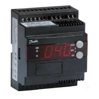
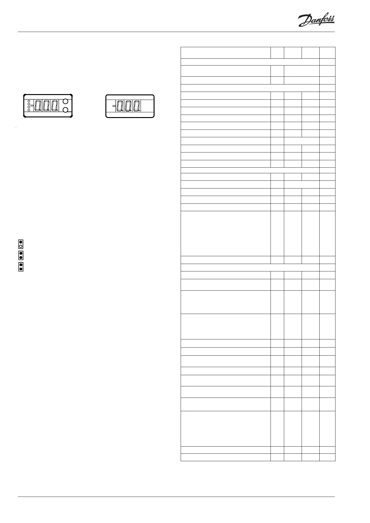
EKA 162
For operation and display of
evaporating pressure. The
light-emitting diodes on the
left-hand side fl ash when
there is an alarm.
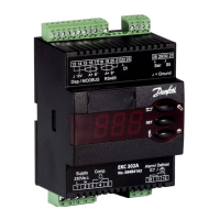
EKA 161
For display of condensing
pressure.
Factory setting
If you need to return to the factory-set values, it can be done in this way:
- Cut out the supply voltage to the controller
- Keep both buttons depressed at the same time as you recon nect the supply voltage
SW: 1.22
Menu survey EKC 531D1
Continues...
Literature survey:
Manual EKC 531D1 RS8DD---
Installation guide, Data communication link RC8AC---
* also applies to regulation with reference displacement
Function
Para-
meter
Min. Max. Factory
setting
Normal display
Shows P0 in EKA 162 (display with but-
tons)
-°C
Shows Pc in EKA 161 - °C
P0 reference
Neutral zone r01 0.1 °C 20 °C 4.0
Correction of signal from P0 sensor r04 -10 °C 10 °C 0.0
Select unit (0=bar and °C, 1=Psig and °F) r05 0 1 0
Start/Stop of regulation r12 OFF ON 1
Reference off set for P0 r13 -20 °C 20 °C 0.0
Set regulation setpoint for P0 r23 -99 °C 30 °C 0.0
Shows total P0 reference r24 °C 0.0
Limitation: P0 reference max. value * r25 -99 °C 30 °C 30.0
Limitation: P0 reference min. value * r26 -99 °C 0 °C -99.9
Displacement of P0 (ON=active “r13”) r27 OFF ON 0
Pc reference
Set regulation setpoint for Pc r28 -25 °C 75 °C 35
Shows total Pc reference r29 °C 10
Limitation: Pc referencen max. value r30 -99 °C 99 °C 99.9
Limitation: Pc referencen min. value r31 -99 °C 99 °C -99.9
Correction of signal from Pc sensor r32 -10 °C 10 °C 0.0
Pc reference variation.1 and 2 are PI-
regulation
1: Fixed reference. “r28” is used
2: Variable reference. Outdoor tempera-
ture (Sc3) included in the reference
3: As 1, but with P-regulation (Xp-band)
4: As 2, but with P-regulation (Xp-band)
r33 1 4 1
Reference off set for Pc r34 -20 °C 20 °C 0.0
Capacity
Min. ON time for relays c01 0 min 30 min. 0
Min. time period between cutins of same
relay
c07 0 min. 60 min 4
Defi nition of regulation mode
1: Sequential (step mode / FILO)
2: Cyclic (step mode / FIFO)
3: Binary and cyclic
c08 1 3 1
If a regulation mode with unloaders is
selected, the relay must be defi ned to:
0: Cut in when more capacity is required
1: Cut out when more capacity is required
c09 0 1 0
Regulation parameter for + Zone c10 0.1 K 20 K 4.0
Regulation parameter for + Zone c11 0.1 min 60 min 4.0
Regulation parameter for ++ Zone c12
0.1
min.
20 min 2.0
Regulation parameter for - Zone c13 0.1 K 20 K 4.0
Regulation parameter for - Zone c14
0.1
min.
60 min 1.0
Regulation parameter for - - Zone c15
0.02
min.
20 min 0.5
Defi nition of compressor connections.See
options on page 10.
c16 0 26 0
The following “c17” to “c28” is only relevant
if “c16” has been selected to 0.
A code will then have to be set for the
relays that are to be ON at the diff erent
steps:
Step 1 (M&M operation)
c17 0 15 0
Step 2 (M&M operation) c18 0 15 0
Step 3 (M&M operation) c19 0 15 0
 Loading...