Do you have a question about the Danfoss FCM 300 and is the answer not in the manual?
Describes the scope and content of the manual, including supported products and software versions.
Outlines prerequisites for using the manual and understanding the PROFIBUS communication.
Specifies prerequisite knowledge for using the PROFIBUS communication with Danfoss equipment.
Details setting parameters for PROFIBUS DP communication, including P904, P918, and 502-508.
Explains automatic baudrate adjustment by the devices based on master configuration.
Refers to further documentation for detailed DP V1 features and helpful specifications.
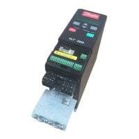
Explains the role of frequency converters as slaves in a PROFIBUS system, communicating with masters.
Identifies PLCs or PCs as masters and frequency converters as slaves in the PROFIBUS system.
Illustrates a single master system with multiple slaves using DP V0 and lists communication requirements.
Details cyclical data exchange and fixed acyclical parameter access for Master Type 1.
Details dynamic acyclical connections and general parameter access for Master Type 2.
Provides a table of maximum drop cable lengths based on transmission speed and lists bus cable properties.
Explains the relationship between cable length, transmission speed, number of segments, and nodes.
Covers physical connection, EMC precautions, and earth connection for the interface.
Details connecting the cable screen and earth for low impedance and interference-free operation.
Advises on cable routing and separation from motor/brake cables for FCM 300.
Covers physical connection, EMC precautions, and earth connection for the interface.
Details connecting the cable screen and earth for low impedance and interference-free operation.
Advises on cable routing and separation from motor/brake cables for FCD 300.
Explains bus termination using RS485 switches for FCD 300 and VLT 2800.
Describes the bus LED indicators for FCD 300, including baud rate search and communication status.
Shows switch settings for configuring the PROFIBUS node address on the FCD 300.
Illustrates the ON/OFF switch settings for RS485 bus termination on the FCD 300.
Covers physical connection, EMC precautions, and earth connection for the interface.
Details connecting the cable screen and earth for low impedance and interference-free operation.
Advises on cable routing and separation from motor/brake cables for VLT 2800.
States support for PROFIBUS DP (EN 50170 part 3) and the need for a DP-supporting master.
Defines PPO (Parameter-Process Data Object) and lists available types (1-8) with byte structures.
Explains PCA structure, fault codes, and how PCA handles parameter tasks.
Describes how the RC part of PCA defines requests and PVA transmits parameter values.
Lists supported data types, time difference, bit sequence, and standardized value representation.
Describes how spontaneous messages are activated by parameter changes and transmitted to partners.
Details SYNC/UNSYNC command usage for synchronized reactions and speed reference examples.
Explains FREEZE/UNFREEZE for simultaneous data reading, with output current examples.
Details the bit assignments for control words according to PROFIDRIVE and FC Control Word standards.
Explains the PPO structure and its PCV/PCD components with an example.
Highlights parameters 502-508, 512, and 515-543 requiring special attention.
Covers protocol selection (800) and bus time out functions (803, 804).
Describes how to configure the function of control word bit 10 for various scenarios.
Details parameters for delayed speed changes (825, 826) and fieldbus enabling (833).
Covers fieldbus enabling (833) and extended diagnosis configuration (849).
Allows selecting the PPO type for DP communication and describes PPO types 1-8.
Allows assigning parameters to PCD 3-10 for writing (915) and reading (916).
Enables or disables spontaneous messages for warnings or alarms.
Explains methods for setting the unique station address for PROFIBUS slaves.
Controls PCV operating authority (927) and process control authority (928).
Allows reading warning messages via bus and lists bit assignments for warnings.
Provides identification and profile number for a Profibus slave.
Provides read-only access to control word (967) and status word (968) via Profibus.
Allows setup selection (970) and data storage options (971).
Lists defined (980-982) and modified (990-992) parameters.
Notes that read-only parameters are not registered as modified even if changing.
Explains accessing parameters via PLC or HMI, considering parameter setup selection.
Shows Hex format for warning, status, and alarm words, and their corresponding bit meanings.
Explains methods for setting the unique station address for PROFIBUS slaves.
Describes how to receive alarm and warning information via extended diagnosis.