Quick Start Guide | ICM/ICAD Motorized Valves - Installation, Programming, and Troubleshooting
© Danfoss | DCS (MWA) | 2016.07
DKRCI.EI.HT0.B3.22 | 520H4763 | 8
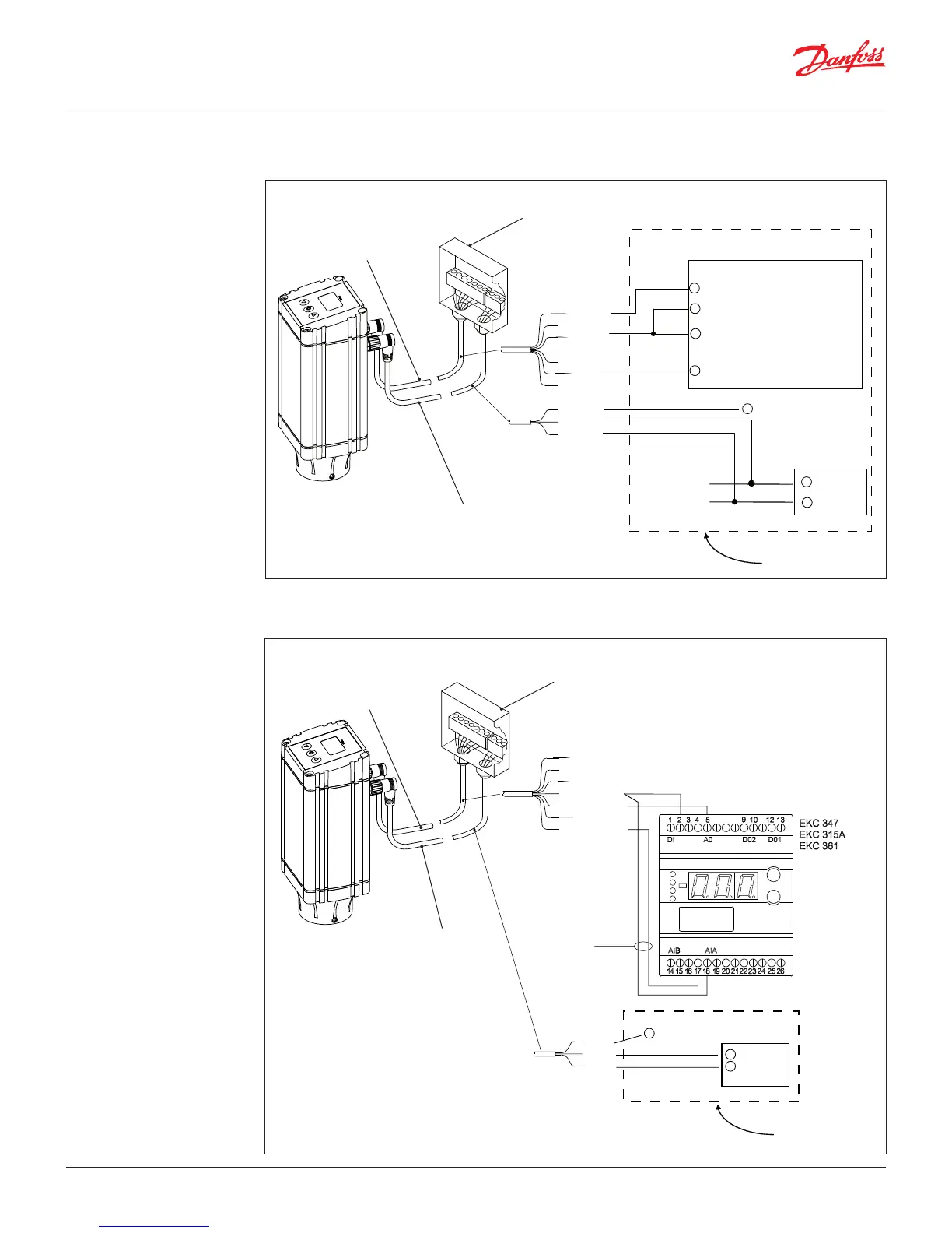
Wiring the ICAD actuator Wiring diagram showing ICAD wired to a PLC or other type of third party electronics
Note: The ICAD supplies the power for the 4-20 mA feedback signal.
9GF
3RZHU
6XSSO\
White
Brown
Yellow
Orange
PLC
Blue
Active 4-20 mA PLC output to control ICAD
Passive 4-20 mA PLC input
for valve position feedback
Passive 4-20 mA PLC input
for valve position feedback
Black
Optional UPS/battery back up
Active 4-20 mA PLC output to control ICAD
+
+
+
-
-
+
-
Power supply cable
Control cable
Terminal box
(customer supplied)
Wiring diagram showing ICAD wired to a Danfoss EKC controller
Note: For instructions on completely wiring an EKC controller, please see the relevant EKC controller manual.
Orange(ground)
Yellow
Blue (+ 4-20 mA)
White
Brown
Optional position
feedback
Only possible
with EKC 347
24 V d.c
Power
Supply
(+ 4-20 mA)
Black
+
-
Optional UPS/battery back up
+
CUSTOMER SUPPLIED
Power supply cable
Control cable
Terminal box
(customer supplied)
 Loading...