Description and selection
options
Alterna‐
tive
Modbus
address
Pass‐
word
level to
Read -
Write
Read
only
(RO) /
Read
Write
(RW) /
Write
(W)
Type of A0 signal for valve
position. This selection
must match the output ex-
pected to read this external-
ly. AO signal calculation is
based on the encoder when
encoder operation (ID15) is
on, else on internal counter.
2: 4-20 mA; 1: 0-20 mA; 0:
no signal
Dene if an Uninterrupti‐
ble Power Supply (UPS) is
applied to the ICAD. This
enables A4 alarms (Low volt-
age of UPS supply).
1: Yes: UPS is attached
0: No: Nothing attached
Denes when the health
indication of a UPS can be
considered as good. Only
active if UPS supply (ID21) is
set to yes. This enables the
UPS signal of health alarm
(A14) and shows the health
state of the UPS for ICAD.
2: DI Low: good health;
1: DI High: good health;
0: O: no UPS health detec-
tion
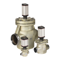
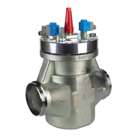
ICM and ICMTS Motorized Valves with ICAD Actuators
© Danfoss | Climate Solutions | 2024.01 BC465027827472en-000102 | 22