6
VIIFR102 © Danfoss 03/2014
Installation manual Danfoss Link™ HP kit
C Read the safety precautions before beginning the
electrical installation.
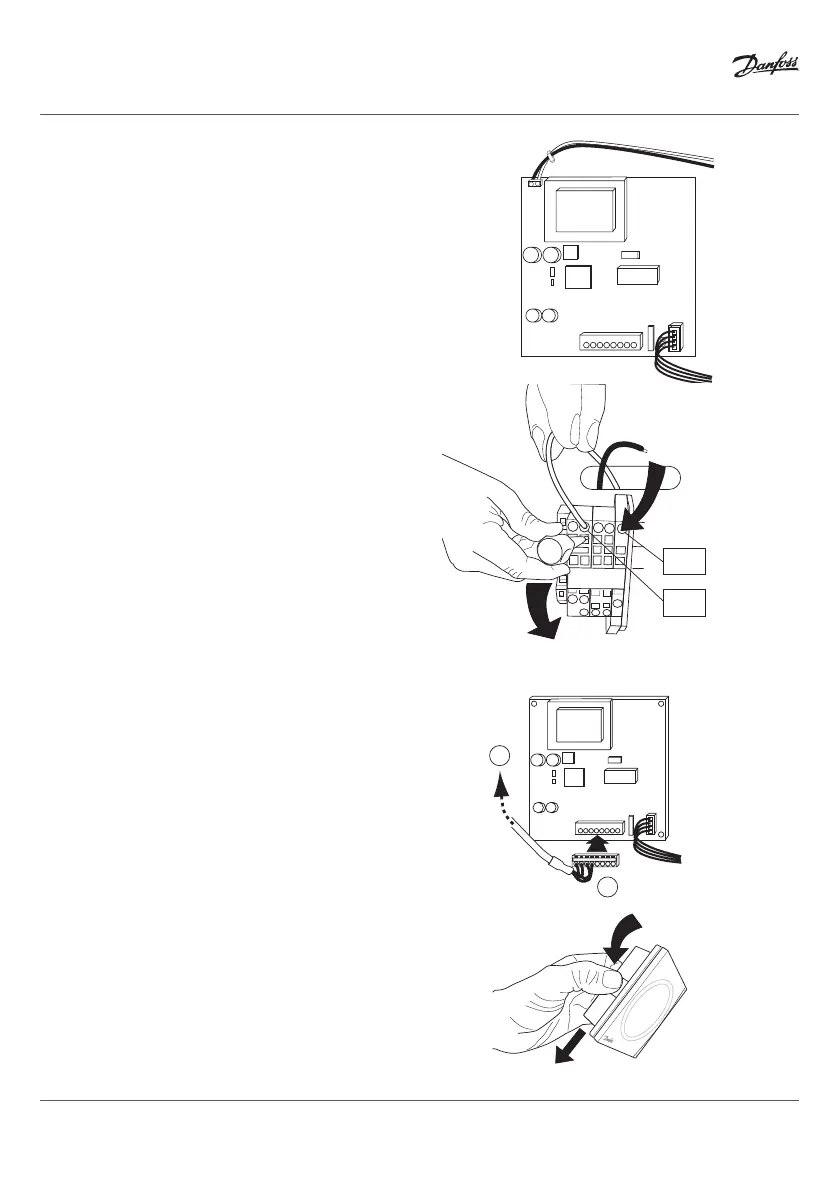
1. Connect the enclosed wires to the GateWay card con-
tact marked 230VAC q.
2. Connect the other end of the cable to the terminal
block on the electrical panel.
3. Connect the blue cable to connection point N1b and
the black cable to connection point 217 in the terminal
bank.
4. To connect the cables:
• Insert a flat screwdriver in the hole below the hole
in which the cable is to be installed. Next, press the
screwdriver downwards to release locking mecha-
nism q.
• Insert the stripped section of the cable into the
upper hole while pulling the screwdriver out at the
same time. Make sure that the cable is securely in
place in the terminal.
Fitting DCM03
COM
2
1
COM
q
Electrical Installation
1. Attach the DCM03 cable to the GateWay card q. Route
the DCM03 cable w up through the inside of the heat
pump and out again through the cable bushing on
the top.
2. Remove the rear panel of the DCM03 unit by pressing
in the spring-loaded plates on the sides q and pull the
rear panel downwards w so that it can be removed.
q
N1
N1b
215
216
217
N1b
217