12
MG.10.P2.22 VLT is a registered Danfoss trade mark
7. Install
Control Card
Cassette
• Connect Modbus signal wire (RTxD+) to
pin 1 of RS-485 terminal block.
• Connect Modbus signal wire (Com) to pin
2 of RS-485 terminal block.
• Connect Modbus signal wire (RTxD-) to pin
3 of RS-485 terminal block.
• Plug RS-485 terminal block into connector
at right side of Modbus option card.
IP54/NEMA 12 Drives
• Close front cover panel and fasten with
captive screws.
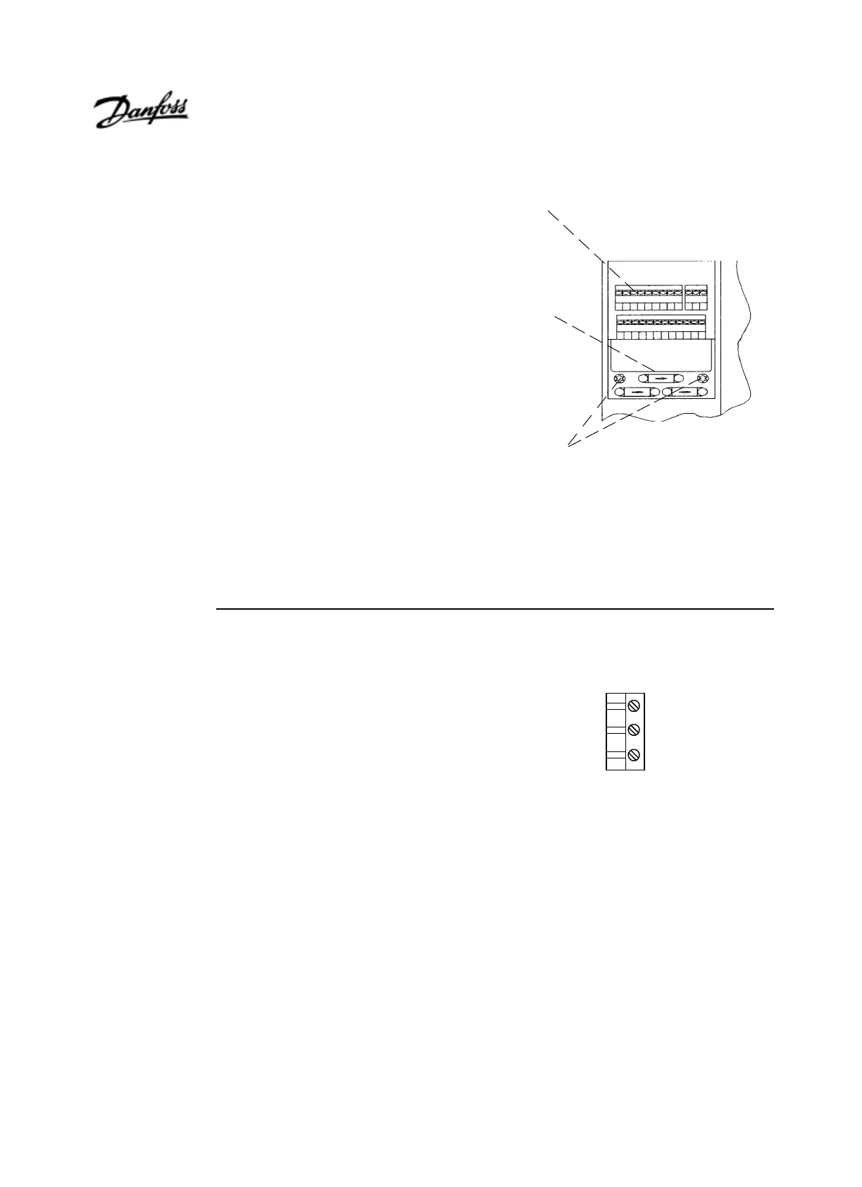
8. Plug in
Terminal
Connector
• Fasten control card cassette by alternately
tightening two captive screws (A).
• Route control wires through clamp
fasteners (B) and secure clamps with two
screws.
• Connect control terminals (C) by firmly
pressing them into connector receptacles.
IP20/NEMA 1 Drives
• Install LCP by sliding bottom into guide slots
on cradle, then press into place ensuring that
connector on back of LCP is engaged.
• Replace protective cover by positioning
guide pins at bottom of cover into holes in
bottom of chassis and snap top of cover
into place.
IP54/NEMA 12 Drives
• Plug cable from LCP into connector on
main control card.
RTxD (+)
RTxD' (-)
Com
RS-485 Connector
Pin 1
(C)
(B)
(A)