16
MG.10.P2.22 VLT is a registered Danfoss trade mark
Translation
from
Modbus
RTU
Protocol to
FC Protocol
Refer to Serial Communication for FC Protocol
in the VLT Operating Instructions for details on
the Danfoss FC protocol used for Modbus serial
communication within the VLT 5000/VLT 6000
Adjustable Frequency Drive.
Parameter Block
PKEPKE
PKEPKE
PKE
PKE contains AK with the parameter
commands and replies, and PNU with the
parameter number. The AK value is
determined by the Modbus function code. Coil
65 decimal determines whether data written
to the drive are stored in EEPROM and RAM
(coil 65 = 1) or just RAM (coil 65 = 0). PNU is
translated from the register address contained
in the Modbus read/write message. The
parameter number is translated to Modbus
as (10 x parameter number)
DECIMAL
.
INDIND
INDIND
IND
IND contains the index. The index is used,
together with the parameter number, for
read/write access. Index has 2 bytes – a low
byte and a high byte. However, only the low
byte is used for indexing. The high byte is used
for reading and writing text. IND is set by a
register in Modbus (40001
HEX
). IND must be
cleared by the Modbus master after reading/
writing text.
PWEPWE
PWEPWE
PWE
HIGhHIGh
HIGhHIGh
HIGh
/PWE/PWE
/PWE/PWE
/PWE
LOWLOW
LOWLOW
LOW
PWE contains the parameter value. The
parameter value block consists of 2 words (4
bytes). The value depends on the command
given (AK). PWE is zero filled on reads. On
writes, PWE is filled with the data field of the
Modbus write message.
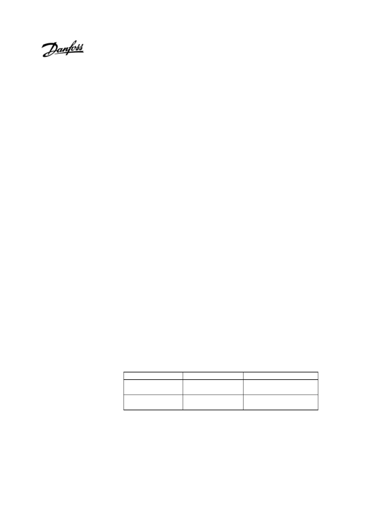
PCD
1
PCD
2
Control packet
(master → slave)
Control word
(Coils 1 – 16)
DEC
Reference value
(Coils 17 – 32)
DEC
Reply packet
(slave → master)
Status word
(Coils 33 – 48)
DEC
Given output frequenc
(Coils 49 – 64)
DEC
PCDPCD
PCDPCD
PCD
11
11
1
/PCD/PCD
/PCD/PCD
/PCD
22
22
2
PCD contains the process word block. The
parameter value block consists of 2 words (4
bytes). The process word block is divided into
two blocks of 16 bits and is stored in Modbus
as status coils. The mapping of the PCD is
shown below.
Process Block Updates
Upon every write to the PCD coils, the process
block is written to the drive and returned from
the drive. On parameter reads and writes, the
PCD is deactivated on messages from the
Modbus option card to the drive. The PCD
coils are updated on response messages from
the drive to the Modbus option card.
Text Blocks
Parameters stored as text strings are
accessed the same as the other parameters
except PWE is replaced with the text block.
The maximum text block size is 20 characters.
If a read request for a parameter is for more
characters than the parameter stores, the
response is space filled. If the read request
for a parameter is for less characters than the
parameter stores, the response is truncated.
PCD Mapping