Instructions
2 | AN23088644237302-000301 - 118A2994A
© Danfoss | Climate Solutions | 2022.05
1 – Introduction
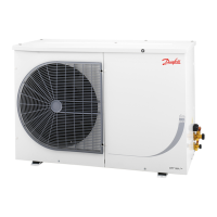
These instructions pertain to Optyma™
Light Commercial range and R290 OP-LCHC,
LCQC,MCGC,MCHC,MCHB,LCNC,MCNC,OP-
SC,SC,PL,BD,TL,FR,NL,FF,NF,DL used for
refrigeration systems
2 – Handling and Storage
• It is recommended not to open the packaging
before the unit is at the nal place for installation.
• Store and transport the unit in an upright
position.
• Store the unit between -35°C and 50°C.
• Don’t expose the packaging to rain or corrosive
atmosphere.
• Unit store and transport must be in comply with
indication on their carton box.
3 – Installation
Do not braze as long as the
condensing unit is under pressure.
It’s not allowed to operate the unit in
ammable atmosphere.
Use a drier with molecular sieves
suitable for R290 (for versions N0,
A09, A11).
Use only dry and clean components
and avoid moisture entering the
system.
Do not lift or move the condensing
unit by using copper tubes. Use Rail
or base provided
Ensure there is sucient distance between the
condenser coil and surrounding to ensure good
air circulation.
Condensing unit must be installed away from
moving components, potential source of
ignition and high temperature.
The unit ambient temperature shall not exceed
50°C during o cycle.
Ensure that the power supply corresponds to
the unit characteristics (See nameplate in unit).
Use clean and dehydrated refrigeration-grade
copper tubes and silver alloy brazing material.
The suction piping connected to the
compressor must be exible in 3 dimensions to
dampen vibrations. Furthermore, piping has to
be done in such a way that oil return for the
compressor is ensured and the risk of liquid slug
over in compressor is eliminated.
Installer must carry out risk assessment for
ammable refrigerant (R290) applications by
referring EN 378 and equivalent European
standards.
Installation, maintenance and commissioning
must be carried out by qualied specialists only!
All connections, example solderings and are
joints, are to be made professionally.
Protect the surroundings against admittance of
unauthorised persons. Pay attention to sucient
ventilation.
Remove transport safety devices, if any.
Mount the condensing unit horizontally. Use
the correct tube diameters.
Prevent any vibrations. Avoid smoking and
open re.
Refrigerant is to be removed and disposed of
professionally.
Assembly of the condensing units
Prepare the tube connections from the
evaporator.
It is recommended to use a drier with 3Å
molecular sieves, e.g. Danfoss type DML.
Use only dry components and avoid moisture
entering the system.
The system components must not contain any
chlorine, mineral oil, or other oily substances.
Maximum test pressure must not exceed 32 bar.
4 – Refrigerant charging
Refrigerant charging (N0, N1, N2, T0, T1, T2,
A00, A01 and A04)
Annex C Fig.2 The process descriptions below
are based on the equipment shown.
1. Suction stop valve
2. Discharge stop valve
3. Connection to suction side
4. Shut-o valve to vacuum pump
5. Shut-o valve to charging cylinder
6. Connection to discharge side
7. Shut-o valve to discharge side
8. Shut-o valve to suction side
9. Connection to vacuum pump
10. Connection to charging cylinder
When a vacuum of 0.5 mbar or lower has been
reached, shut o the connection to the vacuum
pump by closing all manifold valves.
Repeat the evacuating process once or twice if
necessary and then close all manifold valves.
Close the service connector of the suction stop
valve (1) by turning the spindle „anticlockwise“
to the rear stop.
Refrigerant charging must take place from
equipment not contaminated with refrigerants
containing chlorine.
For units with stop valves the rule is that
refrigerant should always be charged in liquid
form through the discharge stop valve of the
unit in order to avoid liquid hammer when the
unit is started. If this rule cannot be observed
the compressor is not to be started until the
pressure and the temperature of the
refrigerating system have been equalized.
Open valves (5) and (7) of the valve manifold
while keeping the other valves closed.
When all liquid has been transferred to the
discharge side of the unit close the service
connector of the discharge valve (2) by turning
the spindle anticlockwise to the rear stop.
Remove all hose connections.
Fit the union nuts with blind caps on pressure
gauge connectors (1) and (2).
Fit and tighten up caps on the valve spindles.
5 – Evacuation
Evacuation (N2, T2, A01 and A04)
Annex C Fig. 2. The process descriptions below
are based on the equipment shown.
1. Suction stop valve
2. Discharge stop valve
3. Connection to suction side
4. Shut-o valve to vacuum pump
5. Shut-o valve to charging cylinder
6. Connection to discharge side
7. Shut-o valve to discharge side
8. Shut-o valve to suction side
Installation and servicing of the condensing units by qualied personnel only. Follow these instructions and sound refrigeration engineering practice
relating to installation, commissioning, maintenance and service.
The condensing unit must only be used for its designed purpose(s) and within its scope of application and according to instruction.
Under all circumstances, the EN378 (or other applicable local safety regulation) requirements must be fullled.
The condensing unit must be handled with caution in the vertical position (maximum oset from the vertical : 15°)
Condensing units can be used with refrigerant letter N = R290, necessary care to be taken during installation and servicing.
In case of R290 refrigerants, all components on the refrigeration circuit must be R290 certied. Example: Evaporator.
Relevant Standards and Directive (CE and non CE)
EN 378 -2: Refrigerating Systems And Heat Pumps-Safety And Environmental Requirements.
EN 60335-1: Household And Similar Electrical Appliances – Safety –Part 1: General Requirements
Low Voltage Directive n° 2014 / 35 / UE
Machinary Directive n° 2006 / 42 / CE
EC Pressure directive (PED) no. 2014/68/EU
RoHS Directive 2011-65-EU
WEEE Directive 2012-19-EU
(Other local applicable standards)
Optyma™ Light Commercial
 Loading...