© Danfoss, 2014-03 520L0619 • Rev EB • Mar 2014 3
Proportional
Version
Standard PVE
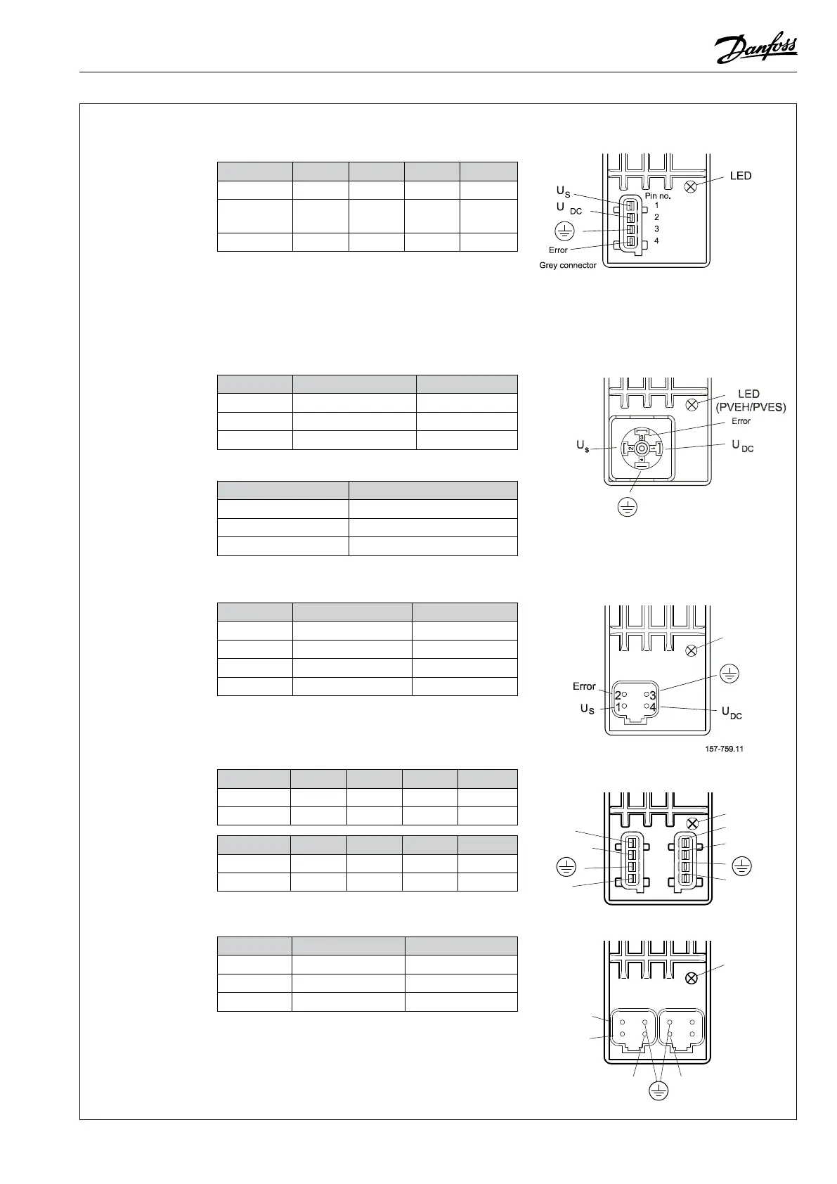
Connection PVEA/PVEH/PVEM/PVES/PVEU - also with
oat B four pin
Connector U
S
U
DC
Gnd Error
AMP
pin 1 pin 2 pin 3 pin 4
Hirschmann/
DIN
pin 2 pin 1 gnd pin 3
Deutsch
pin 1 pin 4 pin 3 pin 2
y On PVEM the error pin is not used and not connected
(pin 3 Hirschmann/DIN).
y Ground pins are internally connected.
Control (U
S
) for standard mounted
PVEA/ PVEH/ PVEM/ PVES
Function
Voltage relative PWM
Neutral 0,5 • U
DC
50%
Q: P → A 0,5 → 0,25 • U
DC
50% → 25%
Q: P → B 0,5 → 0,75 • U
DC
50% → 75%
Control (U
S
) for standard mounted PVEU
Function
PVEU
Neutral 5 V
Q: P → A 5 V → 2,5 V
Q: P → B 5 V → 7,5 V
Control (U
S
) for standard mounted PVEH/PVEM
oat B four pin version
Function
Voltage relative PWM
Neutral 0,5 • U
DC
50%
Q: P → A 0,5 → 0,34 • U
DC
50% → 34%
Q: P → B 0,5 → 0,65 • U
DC
50% → 65%
Float 0,75 • U
DC
75%
Standard PVE with DI
Connection PVE with direction indication (DI)
Connector 1 U
S
U
DC 1
Gnd Error
AMP (grey)
p 1 p 2 p 3 p 4
Deutsch
p 1 p 4 p 3 p 2
Connector 2 DI-B DI-A Gnd U
DC 2
AMP (black)
p 1 p 2 p 3 p 4
Deutsch
p 4 p 3 p 2 p 1
Control (U
S
) for standard mounted PVEA–DI/ PVEH–DI
Function
U
S
PWM
Neutral 0,5 • U
DC
50%
Q: P → A 0,5 → 0,25 • U
DC
50% → 25%
Q: P → B 0,5 → 0,75 • U
DC
50% → 75%
y Ground pins are internally connected.
y U
DC2
only supplies electronics for feedback signal and
error pin on PVEA-DI / PVEH-DI. Two separate power
sources can be used.
LED
AMP version PVEA/PVEH/PVES/PVEU
Deutsch version PVEA/PVEH/PVES/PVEU/
PVEH oat B
Hirschmann/DIN version PVEH/PVEM/PVES/
PVEH oat B/PVEM oat B
Black connector
Grey connector
DI-B
DI-A
1
2
4
3
Pin no.
LED
U
DC1
S
U
Error
U
DC2
AMP version PVEA–DI/PVEH–DI
2
1
Error
3
4
U
S
U
DC
U
DC2
DI-B
DI-A
2
1
3
4
LED
Deutsch version PVEA–DI/PVEH–DI

 Loading...