2 AN00000355xx-04 • Rev 0101 • March 2017 © Danfoss A/S, 2017-03
Montering og orientering af stik
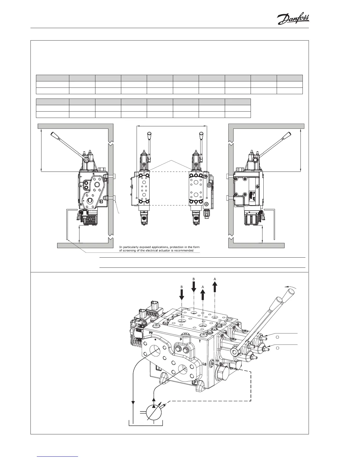
Installation and plug orientation
Montage und Ausrichtung des Steckers
Montage et orientation de la prise
PVB 128 1 2 3 4 5 6 7 8 9
L (mm) 98,5 164,5 230,5 296,5 362,5 428,5 494,5 560,5 626,5
L (in) 3.88 6.48 9.07 11. 67 14.27 16.87 19.47 22.07 24.67
* Plads til demontage / * Room for dismantling / * Platz für Demontage / * Espace pour démontage
4 x M12x18
[4 x 7/16-14UNC x 0.7]
345 [13.6]*
120 [4.7]*
PVB 256 1 2 3 4 5 6 7
L (mm) 118,5 204,5 290,5 376,5 462,5 548,5 634,5
L (in) 4.67 8.05 11.44 14.82 18.21 21.59 24.98
Indstilling af maks. oliestrøm
Setting of max. flow
Einstellung des max. Ölstroms
Réglage de débit maxi
PVP - Tilslutning
PVP - Connection
PVP - Anschluss
PVP - Raccordement
18 ±2 N•m
[159 ±18 lbf•in]
18 ±2 N•m
 Loading...