© Danfoss A/S, 2017-03 AN00000355xx-04 • Rev 0101 • March 2017 5
PVE kontrol specifikationer
PVE control specifications
PVE Steuerungsspezifikationen
PVE spécifications de contrôle
PVE driftsbetingelser
PVE operating conditions
PVE Betriebsbedingungen
PVE conditions de
fonctionnement
PVEO Control Specification
Supply Voltage (U
DC
)
Rated 12 V
DC
24 V
DC
Range 11 → 15 V
DC
22 → 30 V
DC
Max. ripple 5 % 5 %
Control Specification PVEH/H-FLA PVEH-U
Supply Voltage (U
DC
)
Rated / Range 11 → 32 V
DC
11 → 32 V
DC
Max. ripple 5 % 5 %
Signal Voltage (U
S
)
Neutral U
S
= 0.5 • U
DC
U
S
= 5 V
Q: P → A U
S
= (0.5 → 0.25) • U
DC
U
S
= 5 V → 2.5 V
Q: P → B U
S
= (0.5 → 0.75) • U
DC
U
S
= 5 V → 7.5 V
Signal Voltage PWM (U
S
)
Neutral U
S
= 50% DUT
Q: P → A U
S
= 50% → 25% DUT
Q: P → B U
S
= 50% → 75% DUT
PWM Frequency (US) Recommended > 1000 Hz
Input Impedance Rated 12 k Ω
Input Capacitance Rated 100 nF
PVEO, PVEH/H-U/H-FLA Operating Conditions
Pilot Pressure
Nominal 13.5 bar [196 psi]
Minimum 10.0 bar [145 psi]
Maximum 15.0 bar [220 psi]
Storage Temp. Ambient -50°C → 90°C [-58°F → 194°F]
Operating Temp. Ambient -40°C → 90°C [-40°F → 194°F]
Oil Viscosity
Operating range 12 → 75 cSt [65 → 347 SUS]
Minimum 4 cSt [39 SUS]
Maximum 460 cSt [2128 SUS]
Oil Cleanliness Maximum 18/16/13 (acc. to ISO 4406)
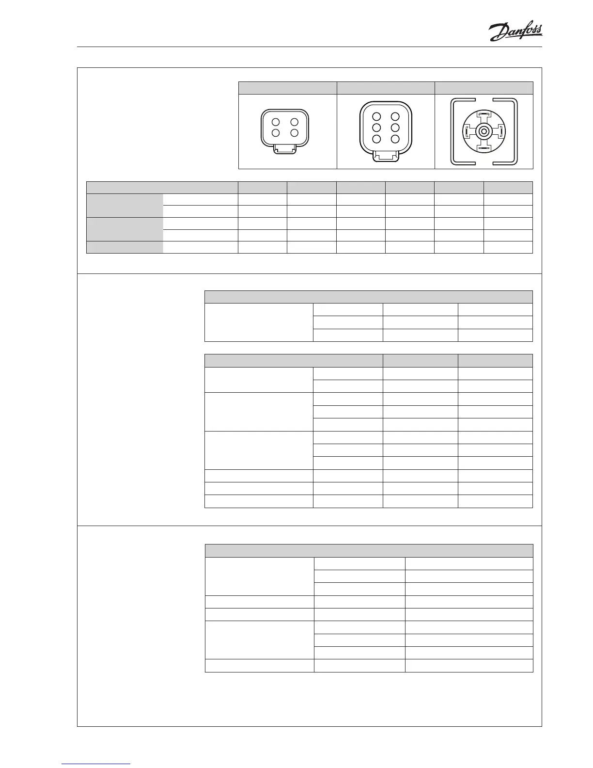
PVE stik varianter
PVE connector variants
PVE Stecker varianten
PVE variantes de connecteur
1x4 DEUTSCH 1x6 DEUTSCH 1x4 DIN
1
2 3
4
5
61
2
3 4
12
3
4
Pin
Pin 1 Pin 2 Pin 3 Pin 4 Pin 5 Pin 6
PVEO
1x4 DEUTSCH U
DC_A
GND GND U
DC_B
1x4 DIN U
DC_A
U
DC_B
GND
PVEH
PVEH-U
1x4 DEUTSCH U
S
Error GND U
DC
1x4 DIN U
DC
U
S
Error GND
PVEH-FLA
1x6 DEUTSCH U
S
Error Float GND U
DC
 Loading...