VLT® 2800 Series
■ Tightening torques, control cables
Control wires must be connected with a tightening
torque of 0.22–0.25 Nm.
■ Electrical installation, control terminals
NOTE
Using unshielded/unarmored cable may not
comply with some EMC/RFI requirements.
Refer to the following table for VLT 2800 terminal
designations and their functional descriptions.
No. Function
01-03 Relay outputs 01-03 can be used for
indicating status and alarms/warnings.
12 24 VDC voltage supply.
18-33 Digital inputs.
20, 55 Common frame for input
and output terminals.
42 Analog output for displaying frequency,
reference, current or torque.
46
1
Digital output for displaying status,
warnings or alarms, as well as
frequency output.
50 +10 VDC supply
voltage for potentiometer or thermistor.
53 Analog voltage input 0 - 10 V DC.
60 Analog current input 0/4 - 20 mA.
67
1
+ 5 VDC supply voltage
to Profibus.
68,
69
1
RS-485, Serial communication.
70
1
Frame for terminals 67, 68 and 69.
Normally this terminal is not to be used.
1. The terminals are not valid for DeviceNet. See the
DeviceNet manual, MG.90.BX.YY for further details.
NOTE
To supply internal 24 VDC voltage to the
digital input terminals, jumper terminal
12 to terminal 27.
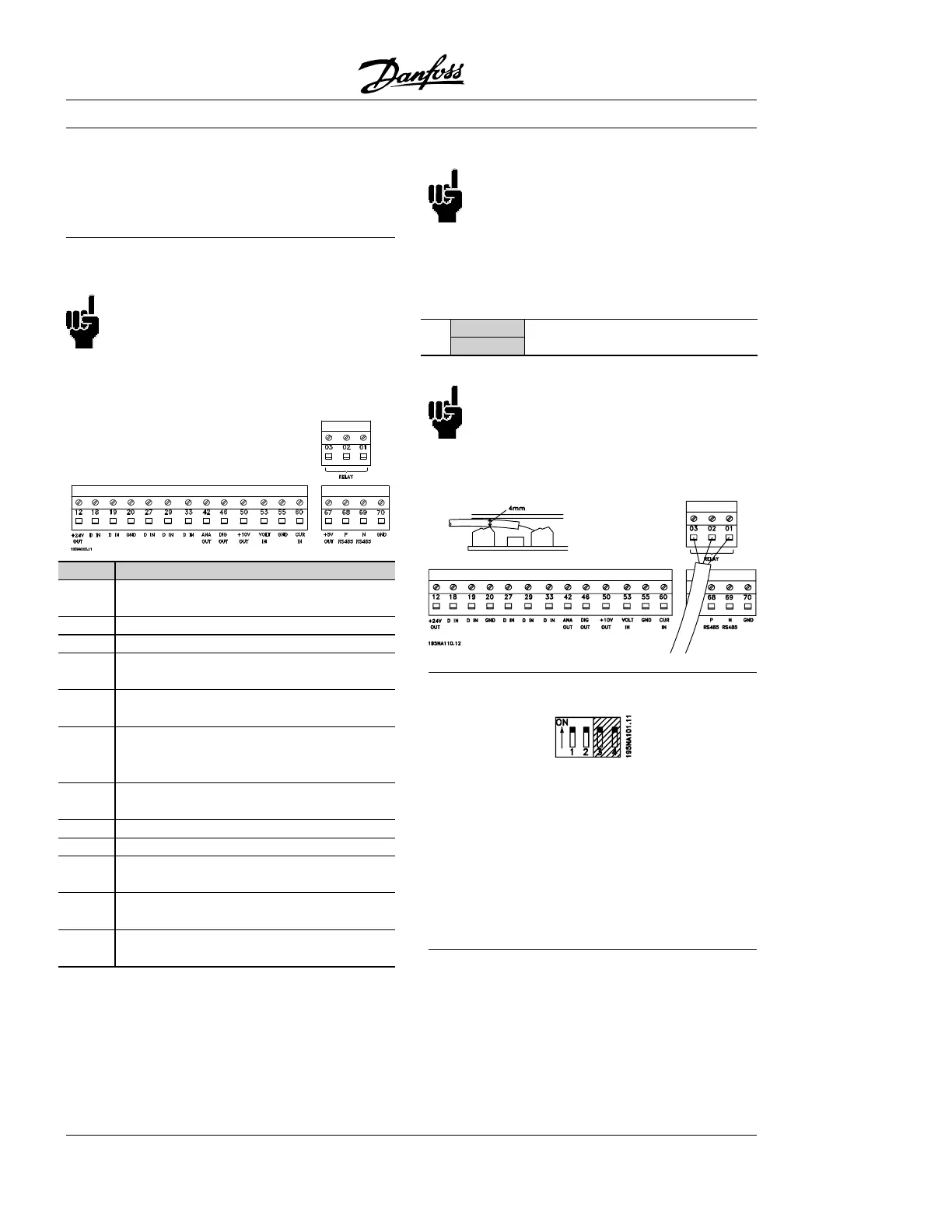
■ Relay connection
See parameter 323, Relay output for programming
of relay output.
No. 01 - 02 1 - 2 make (normally open)
01 - 03 1 - 3 break (normally closed)
NOTE
The cable jacket for the relay must cover
the first row of control card terminals -
otherwise the galvanic isolation (PELV)
cannot be maintained. Maximum cable diameter:
0-160 in (4 mm). See drawing.
■ Profibus DIP switches setting
The dip switch is only on the control card with Profibus
DP communication. The switch position shown is the
factory setting. Switches 1 and 2 are used as cable
termination for the RS-485 interface. If the adjustable
frequency drive is located as the first or last (or only)
unit in the bus system, switches 1 and 2 must be ON.
On the remaining adjustable frequency drives, switches
1 and 2 must be OFF. Switches 3 and 4 are not applied.
MG.28.A8.22 - VLT is a registered Danfoss trademark
20
 Loading...


