VLT
®
6000 HVAC
Installation
■ Electrical installation - earthing of control cables
Generally speaking, control cables must be braided
screened/armoured and the screen must be
connected by means of a cable clamp at both
ends to the metal cabinet of the unit.
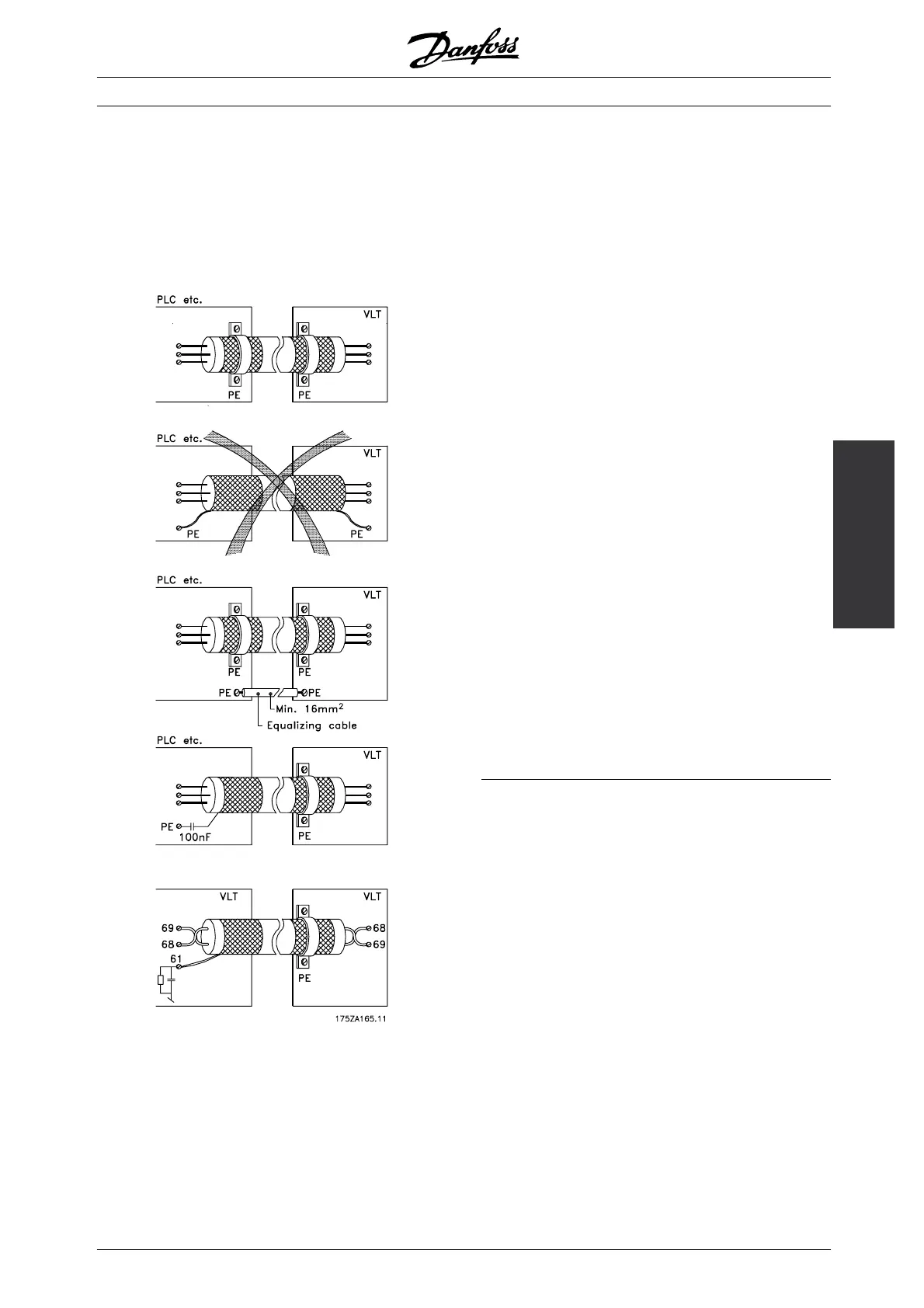
The drawing below indicates how correct earthing is
carried out and what to be done if in doubt.
Correct earthing
Control cables and cables for serial communication
must be fitted with cable clamps at both ends to
ensure the best possible electrical contact
Wrong earthing
Do not use twisted cable ends (pigtails), since these
increase the screen impedance at high frequencies.
Protection with respect to earth potential
between PLC and VLT
If the earth potential between the frequency converter
and the PLC (etc.) is different, electric noise may
occur that will disturb the whole system. This
problem can be solved by fitting an equalising
cable, to be placed next to the control cable.
Minimum cable cross-section: 16 mm
2
.
For 50/60 Hz earth loops
If very long control cables are used, 50/60 Hz earth
loops may occur. This problem can be solved by
connecting one end of the screen to earth via a
100nF capacitor (keeping leads short).
Cables for serial communication
Low-frequency noise currents between two frequency
converters can be eliminated by connecting one end
of the screen to terminal 61. This terminal is connected
to earth via an internal RC link. It is recommended
to use twisted-pair cables to reduce the differential
mode interference between the conductors.
■ Tightening-up torque and screw sizes
The table shows the torque required when fitting
terminals to the frequency converter. For VLT
6002-6032, 200-240 V, VLT 6002-6122, 380-460
and 525-600 V the cables must be fastened
with screws. For VLT 6042-6062, 200-240 V
and for VLT 6152-6550, 380-460 V, the cables
must be fastened with bolts.
These figures apply to the following terminals:
91, 92, 93
Mains terminals (Nos.) L1, L2, L3
96, 97, 98
Motor terminals (Nos.) U, V, W
Earth terminal (Nos.) 94, 95, 99
MG.60.C7.02 - VLT is a registered Danfoss trademark
11

 Loading...


